
Heliostat driving device

A driving device and heliostat technology, which is applied in the field of solar power generation, can solve the problems of high manufacturing cost, large area of ​​the mirror field, and complex structure of the heliostat driving device, so as to reduce frictional resistance, simplify the structure, and improve the photoelectricity. The effect of conversion efficiency

Inactive Publication Date: 2021-08-27
HANGZHOU SINO DEUT POWER TRANSMISSION EQUIP
View PDF9 Cites 0 Cited by
  • Summary
  • Abstract
  • Description
  • Claims
  • Application Information

AI Technical Summary

Problems solved by technology

[0004] However, the existing heliostat driving device has the following technical defects: First, in order to facilitate the control of the horizontal rotation angle, people usually drive the heliostat to rotate in the horizontal plane through a driving motor and a reduction mechanism.
Since the relative movement of the sun is relatively slow, and the movement angle from morning to evening will not exceed 360 degrees, therefore, the reduction mechanism needs a huge reduction ratio, resulting in a complicated structure and high manufacturing cost of the heliostat driving device
[0005] In addition, due to the large area occupied by the mirror field, the location of the heliostat to the central heat collector tower of the mirror field is far away, and the sunlight reflected by the heliostat to the heat sink of the heat collector tower will form a large attenuation, that is, A considerable part of the light energy is wasted in the transmission process, which is not conducive to improving the photoelectric conversion efficiency

Method used


Image

  • Heliostat driving device
  • Heliostat driving device
  • Heliostat driving device

Examples


Embodiment Construction

[0037] The present invention will be further described below with reference to the accompanying drawings.

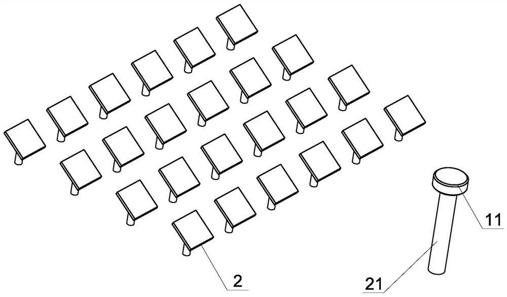
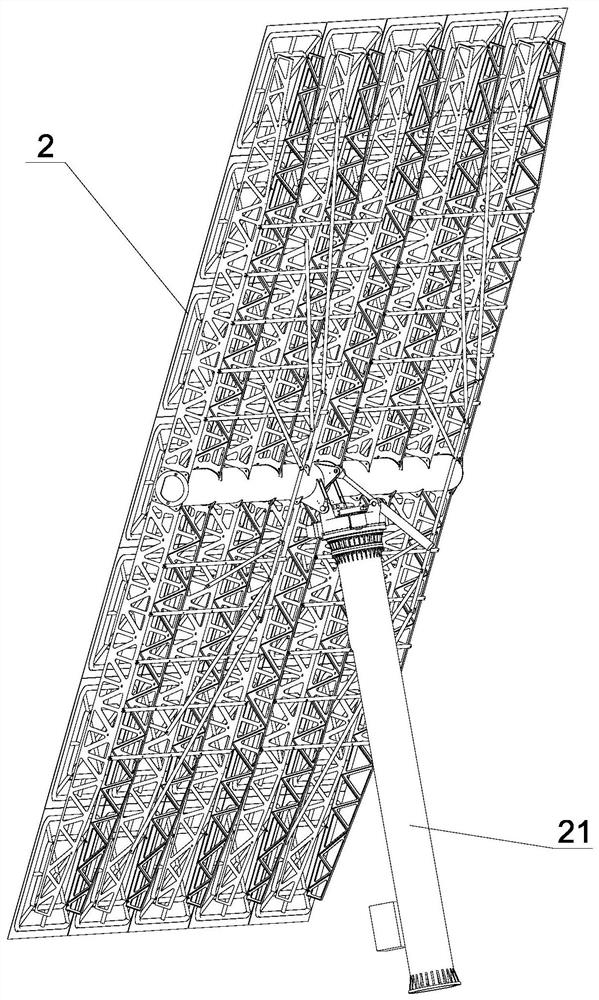
[0038] like figure 1 As shown, a fixed day mirror driving device is suitable for solar thermal power generation systems as a solar thermal power generation system, which includes a collecting tower 1, a heat absorber 11 set in the upper end of the collecting tower, numerous towards a collecting tower Set of fixed day mirrors 2, fixed day mirrors reflect the sun light to the heat absorber of the collector tower, of course, the day is disposed on the column 21. The present invention includes a horizontal rotary drive for driving the level of fixed day mirrors to drive a pitch driving device that rotates in a vertical plane, and swinging through the level of fixed day mirrors, which can make the fixed day mirror The sun rays are tracked according to the geographic latitude of the location, to ensure that the sun is reflected onto the heat absorber of the collecting tower.

[00...


PUM


Abstract

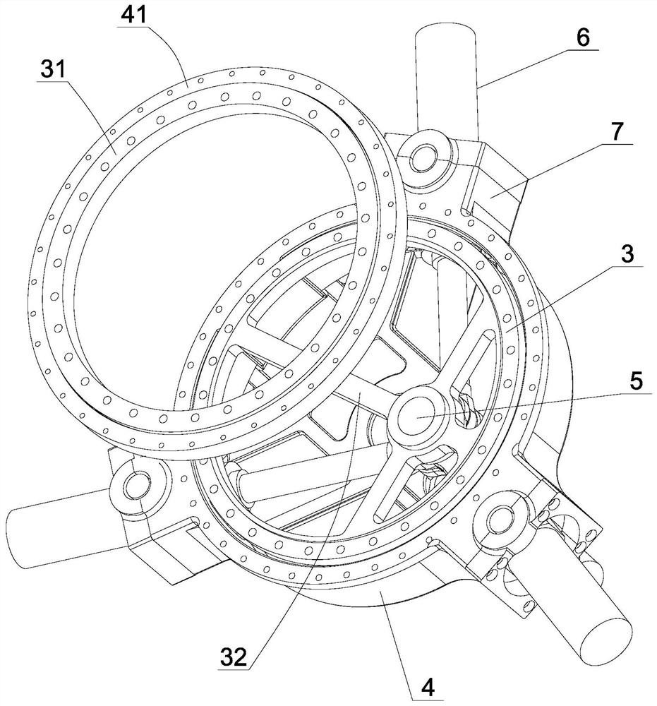
The invention discloses a heliostat driving device which comprises a horizontal rotation driving device and a pitching driving device, wherein the horizontal rotation driving device comprises a pedestal and a base rotatably arranged on the pedestal, an eccentric shaft is arranged on the pedestal, three driving oil cylinders are evenly arranged in the circumferential direction of the pedestal, cylinder bodies of the driving oil cylinders are hinged to the pedestal through hinge seats, the ends of piston rods of the driving oil cylinders are hinged to the eccentric shaft, the hinged seats connected with the first driving oil cylinder and the third driving oil cylinder are located in the same radial direction of the base, the distance between the second driving oil cylinder and the first driving oil cylinder and the distance between the second driving oil cylinder and the third driving oil cylinder are equal, the eccentric distance of the eccentric shaft relative to the rotating center of the base is r, the rotating radius of the hinged seats on the base is R, and r / R is greater than or equal to 0.5 and less than or equal to 0.8. The structure of the heliostat driving device can be simplified so as to ensure that the heliostat can track the movement of the sun and accurately reflect sunlight to a heat absorber, and meanwhile, the photoelectric conversion efficiency is facilitated to be improved.

Description

Technical field [0001] The present invention relates to the field of solar power generation technologies, and more particularly to a fixed day mirror drive. Background technique [0002] With the rapid development of the economy and the continuous increase in people's environmentally friendly, green energy like solar power is increasingly popular. The basic working principle of the solar thermal power generation system is: set a collection of hot tower in an area of ​​virginal field, and set many sets of fixed-day mirrors around the collection tower, and the day can track the sun in the sun to reflect the sun light. On the heat absorber of the mirror center collecting tower, the heat absorber absorbs the light to heat the internal working medium, and then utilize high temperature working media. That is to say, the daylight is an important part of the entire power station that is related to the efficiency of solar power generation. [0003] In the prior art, the daytime mirror is ...

Claims


Application Information

Patent Timeline
Patent Type & Authority Applications(China)
IPC IPC(8): G05D3/12
CPCG05D3/12
Inventor 洪松蒋礼
Owner HANGZHOU SINO DEUT POWER TRANSMISSION EQUIP
Learn More