Cooling disc body with internal annular channel and preparation method of cooling disc body
A technology of annular channel and cooling plate, which is applied in the direction of manufacturing tools, heat exchange equipment, heat treatment equipment, etc., can solve the problems of complex water channel structure and easy mutual influence of branch liquid flow, so as to reduce production cost, good sealing performance, and high-quality products The effect of high pass rate
- Summary
- Abstract
- Description
- Claims
- Application Information
AI Technical Summary
Problems solved by technology
Method used
Image

Examples
preparation example Construction
[0079] The preparation method comprises the following steps:
[0080] (1) Machining the main board 1 and the cover plate 3, forming an annular groove 2 on the main board 1, assembling it with the cover plate 3, and then performing friction stir welding to obtain the combined disc body;
[0081] (2) Carrying out heat treatment and solid solution aging treatment successively to the combined disc body obtained in step (1), cleaning and drying successively after cooling;
[0082] (3) Perform anodic oxidation on the combined disc body treated in step (2) to obtain the cooling disc body.
Embodiment 1
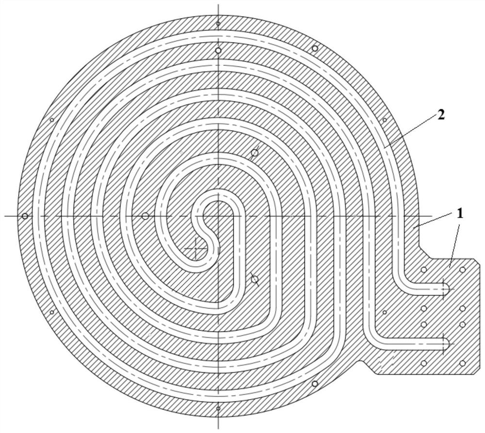
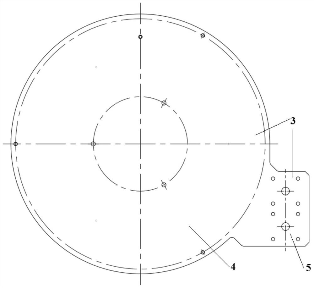
[0085] This embodiment provides a cooling plate body with an internal annular channel, the cooling plate body includes a main board 1 and a cover plate 3, wherein the schematic cross-sectional structure of the main board 1 is shown in figure 1 As shown, the schematic diagram of the top view structure of the cooling plate is as follows figure 2 As shown, the main board 1 is evenly provided with an annular groove 2, and the cover plate 3 is used together with the main board 1 to cover one side of the annular groove 2 on the main board 1, and the annular groove 2 constitutes a cooling plate body the internal annular channel;
[0086] The cooling plate is in the shape of a volute as a whole, including a volute main body 4 and a volute inlet 5, and the inlet and outlet of the annular channel are both arranged at the volute inlet 5 to communicate with the outside world.
[0087] The annular grooves 2 on the main board 1 are coiled at intervals, and there are 6 rings of annular gro...
Embodiment 2
[0095]This embodiment provides a cooling plate body with an internal annular channel, the cooling plate body includes a main board 1 and a cover plate 3, the main board 1 is uniformly provided with an annular groove 2, the cover plate 3 and the main board 1 Matching use, covering the side of the annular groove 2 on the main board 1, the annular groove 2 forms the inner annular channel of the cooling plate;
[0096] The cooling plate is in the shape of a volute as a whole, including a volute main body 4 and a volute inlet 5, and the inlet and outlet of the annular channel are both arranged at the volute inlet 5 to communicate with the outside world.
[0097] The annular grooves 2 on the main board 1 are coiled at intervals, and four rings of the annular grooves 2 are provided.
[0098] The depth of the annular groove 2 is 40% of the thickness of the main board 1 .
[0099] The cross-sectional shape of the annular groove 2 is rectangular.
[0100] The thickness of the main boa...
PUM
| Property | Measurement | Unit |
|---|---|---|
| Thickness | aaaaa | aaaaa |
| Thickness | aaaaa | aaaaa |
| Thickness | aaaaa | aaaaa |
Abstract
Description
Claims
Application Information
 - Generate Ideas
- Intellectual Property
- Life Sciences
- Materials
- Tech Scout
- Unparalleled Data Quality
- Higher Quality Content
- 60% Fewer Hallucinations
Browse by: Latest US Patents, China's latest patents, Technical Efficacy Thesaurus, Application Domain, Technology Topic, Popular Technical Reports.
© 2025 PatSnap. All rights reserved.Legal|Privacy policy|Modern Slavery Act Transparency Statement|Sitemap|About US| Contact US: help@patsnap.com