
Foaming equipment for producing polyurethane foam plastic and production process

A foamed plastic and foaming equipment technology, applied in the field of polyurethane foam, can solve the problems of unmatched fine-tuning to achieve the best foaming effect, poor foaming effect of foaming equipment, poor performance of polyurethane foam, etc. Good foaming effect, improving foaming effect and speeding up foaming speed

Active Publication Date: 2021-08-27
HUIZHOU YUANAN NEW MATERIALS
View PDF6 Cites 0 Cited by
  • Summary
  • Abstract
  • Description
  • Claims
  • Application Information

AI Technical Summary

Problems solved by technology

[0003] When the existing polyurethane foam foaming equipment is filled with foaming raw materials, the ratio of the two main raw materials is usually fixed, and the properties of the polyurethane foam are different, so the addition ratio of the two main raw materials is also different. The foaming equipment cannot be fine-tuned according to the shape, strength and function of the foaming molding to achieve the best foaming effect. The foaming effect of the foaming equipment is poor, and the performance of the polyurethane foam after molding is poor. Therefore, we propose A foaming equipment for polyurethane foam production

Method used


Image

  • Foaming equipment for producing polyurethane foam plastic and production process
  • Foaming equipment for producing polyurethane foam plastic and production process
  • Foaming equipment for producing polyurethane foam plastic and production process

Examples


Embodiment

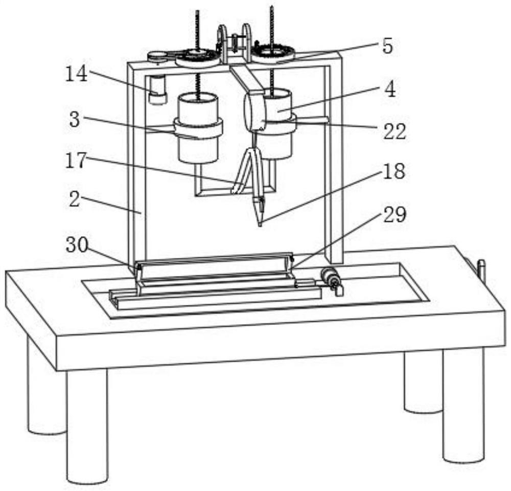
[0045] Example: Reference Figure 1-9 The shown foaming equipment for polyurethane foam production includes a workbench 1 . The workbench 1 can be any base structure in the prior art, such as a metal plate body.

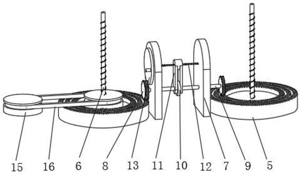
[0046] An installation frame 2 is fixedly installed on the top side of the workbench 1, and the installation frame 2 may be any frame structure in the prior art, and two multi-layer ring gears 5 are rotatably installed on the top side of the installation frame 2.

[0047] Both sides of the installation frame 2 are far away from each other and are fixed with round shafts on the inner walls, and one end of the two round shafts is fixed with a fixed ring 3, and the fixed ring 3 can be any metal ring in the prior art. Reagent cartridges 4 are fixedly sleeved inside the fixing rings 3, and the reagent cartridges 4 may be any kind of cartridge mechanism in the prior art, such as metal cartridges.

[0048] Pistons are movably socketed in the two reagent cylinders 4, and i...


PUM


Abstract

The invention discloses foaming equipment for polyurethane foam plastic production and a production process, and relates to the field of polyurethane foam. The foaming equipment comprises a workbench, a mounting frame is fixedly mounted on the top side of the workbench, and two multi-layer gear rings are rotatably mounted on the top side of the mounting frame; circular shafts are fixedly mounted on the inner walls of the two sides, away from each other, of the mounting frame correspondingly, and fixing rings are fixedly mounted at the ends, close to each other, of the two circular shafts correspondingly. A rotating disc is rotated to drive an adjusting lead screw to rotate, the adjusting lead screw rotates to drive a U-shaped block to move, the U-shaped block moves to drive a lantern ring to move, the lantern ring moves to drive two gears to slide on the two multi-layer gear rings through a rotating shaft, and therefore injection proportion of two raw materials is adjusted by adjusting transmission ratio of rotation of the two multi-layer gear rings, the best foaming effect can be achieved by finely adjusting the proportion according to different shapes, strengths and functions of foaming forming, foaming effect of the foaming equipment is good, and performance of the formed polyurethane foam plastic is good.

Description

technical field [0001] The invention relates to the field of polyurethane foam, in particular to a foaming equipment and production process for producing polyurethane foam plastics. Background technique [0002] Polyurethane foam is a high molecular polymer made of isocyanate and polyether as the main raw materials, mixed by special equipment under the action of various additives such as foaming agent, catalyst, and flame retardant, and foamed on-site by high-pressure spraying. There are two types of polyurethane foam, soft foam and hard foam. The soft foam has an open-cell structure, and the hard foam has a closed-cell structure. Foam is commonly used in sofa furniture, pillows, cushions, toys, clothing and soundproof linings. [0003] When the existing polyurethane foam foaming equipment is filled with foaming raw materials, the ratio of the two main raw materials is usually fixed, and the properties of the polyurethane foam are different, so the addition ratio of the two...

Claims


Application Information

Patent Timeline
Patent Type & Authority Applications(China)
IPC IPC(8): B29C44/34B29C44/38B29C44/42B29C44/58
CPCB29C44/3442B29C44/386B29C44/424B29C44/428B29C44/58B29C44/34
Inventor 董凤云陆兴益
Owner HUIZHOU YUANAN NEW MATERIALS
Learn More