Novel electrocardiograph storage device

A technology of electrocardiography machine and storage device, which is applied in the field of new electrocardiography machine storage device, which can solve the problems of lack of lead wire electrode head protection and complicated operation, and achieve the effects of small appearance, good stability, and improved work efficiency and service quality

Pending Publication Date: 2021-08-27
上海市静安区共和新路街道社区卫生服务中心
View PDF1 Cites 0 Cited by
  • Summary
  • Abstract
  • Description
  • Claims
  • Application Information

AI Technical Summary

Problems solved by technology

But it solves the problem of direct and rapid use of lead wires, and its first storage mechanism is equipped with multiple independent boxes, the operation is complicated, and it lacks protection for the electrode heads of lead wires

Method used


Image

  • Novel electrocardiograph storage device
  • Novel electrocardiograph storage device
  • Novel electrocardiograph storage device

Examples


Embodiment 1

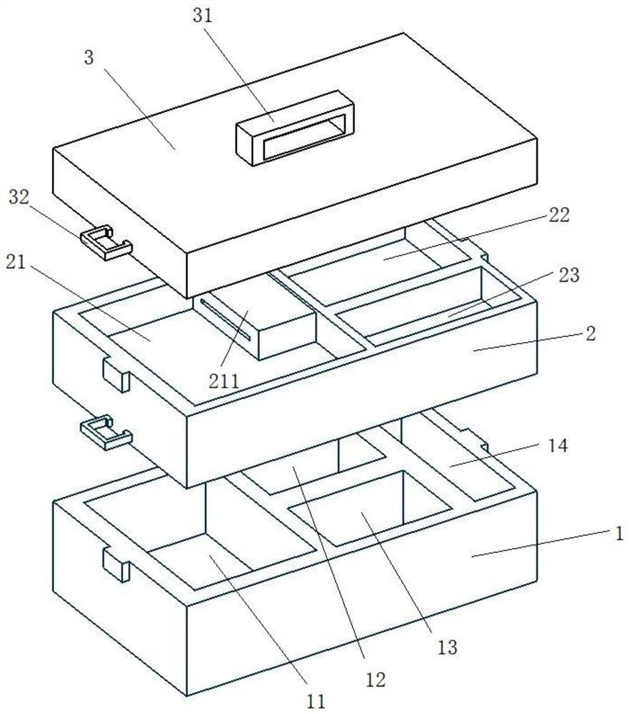
[0034] Please see attached figure 1 , with figure 1 It is a schematic diagram of the new electrocardiograph storage device of the present invention. A novel electrocardiograph storage device, comprising an operating layer 1, a tool layer 2, and a protective cover 3;

[0035] The top of the protective cover 3 is provided with a handle 31 to facilitate the transfer of the storage device. A buckle 32 is provided at the center of the bottom of the two ends of the protective cover. Adaptively connected with the buckle 32;

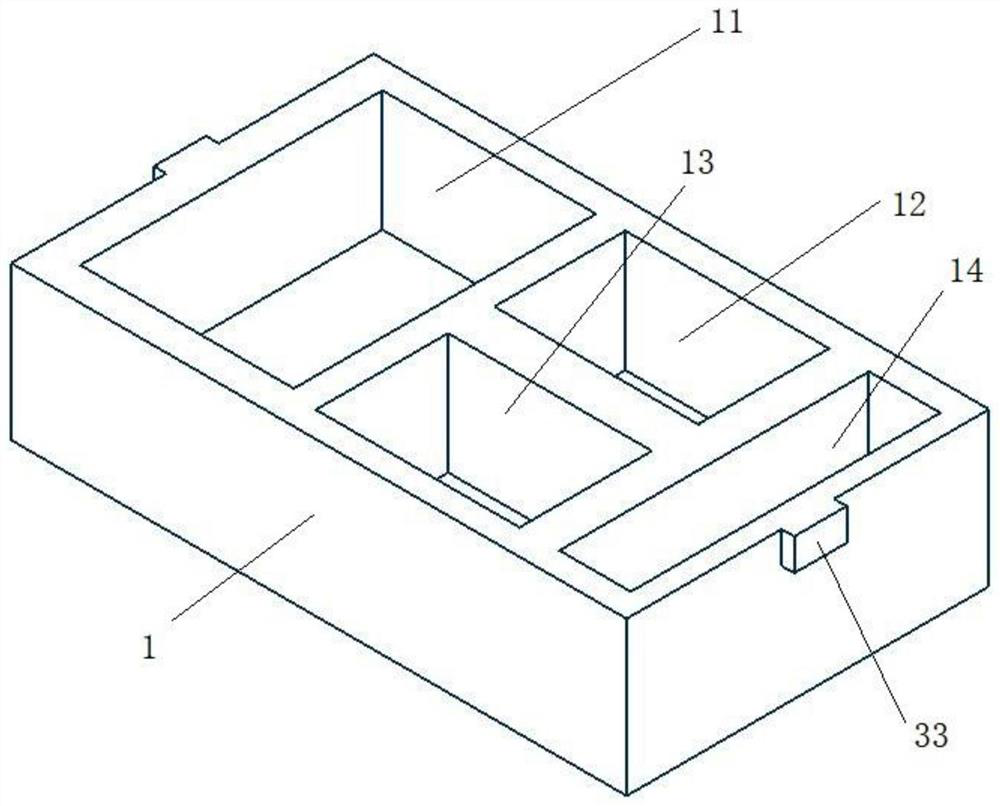
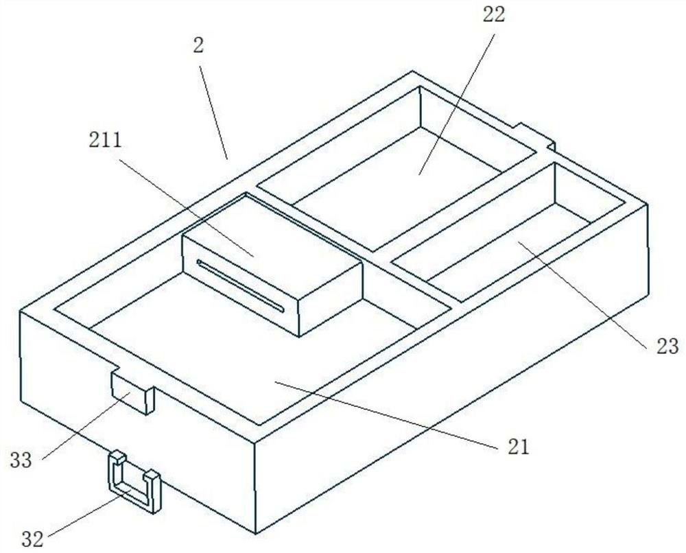
[0036] Please see attached figure 2 , with figure 2 It is a schematic diagram of the operation layer of the new electrocardiograph storage device of the present invention. The operation layer 1 is provided with an electrocardiogram machine storage area 11, a disinfection product storage area 12, a dirt storage area 13, and a holding tool storage area 14; the electrocardiogram machine storage area 11 is compatible with existing portable electrocardiogram m...

Embodiment 2

[0042] This embodiment is basically the same as Embodiment 1, the difference is that please refer to the attached Figure 6 , with Figure 6 It is a schematic diagram of the operating layer elastic bands of the novel electrocardiogram machine storage device of the present invention; two elastic bands 4 are arranged in the disinfection product storage area 12 and the dirt storage area 13, and the elastic bands 4 are horizontally and vertically arranged. Better stability of the cans placed therein, especially for inappropriately sized cans or when securing multiple cans; see attached Figure 7 , with Figure 7 It is a schematic diagram of the tool layer elastic belt of the new electrocardiogram machine storage device of the present invention; the lead line storage area 21, the document storage area 22, and the recording tool storage area 23 are provided with a straight elastic belt 4, which can effectively prevent it. Items inside accidentally poured out.


PUM


Abstract

The invention relates to a novel electrocardiograph storage device. The device comprises an operation layer, a tool layer and a protective cover; the tool layer is detachably connected with the operation layer, and the protective cover is detachably connected with the tool layer; an electrocardiograph storage area, a disinfection article storage area, a dirt storage area and a holding tool storage area are arranged on the operation layer, the disinfection article storage area is lower than an disinfection article tank, and the dirt storage area is lower than a dirt collection tank; a lead wire storage area, a file storage area and a recording tool storage area are arranged on the upper layer of a working layer; and the lower layer of the working layer is provided with a number of covering areas which are respectively adapted to the electrocardiograph storage area, the disinfection article storage area, and the dirt storage area. The device has the advantages that: the device is practical, convenient, environmentally friendly, neat, small and exquisite, articles can be prevented from toppling over in the using and transporting process, lead wire electrode tips can be effectively protected, effective storage of articles is facilitated, and service quality is improved.

Description

technical field [0001] The invention relates to the field of medical equipment, in particular to a novel electrocardiograph storage device. Background technique [0002] At present, in medical institutions, in community health service stations and patients' homes, portable electrocardiograph equipment is placed in simple plastic bags or individual small boxes. In clinical work, when medical personnel carry out electrocardiogram examinations for patients, it is relatively simple to place items for the electrocardiogram machine. During the transportation of the ECG machine, it is easy to confuse the ECG wires, saline cotton ball tank, holding forceps, dirt tank, etc., and these supplies need to be rearranged before the ECG machine is used. The fixity of the items is poor, the compatibility between different types of items is poor, and the protection of the lead wires is not enough, so the electrode heads are easily damaged due to collisions. [0003] Chinese patent applicati...

Claims


Application Information

Patent Timeline
IPC IPC(8): A61B5/332A61B5/321A61B50/31
CPCA61B50/31A61B2050/0065A61B2050/3011
Inventor 张培张辉映黄斌
Owner 上海市静安区共和新路街道社区卫生服务中心
Why Eureka
Try Eureka