
Manufacturing method of single-optical-fiber cascade type temperature-depth-salinity sensor for deep sea exploration

A production method and a single optical fiber technology, which are applied in the direction of transmitting sensing components, converting sensor output, and instruments with optical devices, can solve problems such as signal strength weakening, microstructure damage, and unfavorable high-efficiency mass production, and achieve compensation for optical transmission loss. , Simple preparation process, easy and efficient mass production

Active Publication Date: 2021-08-24
DALIAN UNIV OF TECH
View PDF5 Cites 2 Cited by
  • Summary
  • Abstract
  • Description
  • Claims
  • Application Information

AI Technical Summary

Problems solved by technology

Although this series of sensing probes has the advantages of compact structure and miniaturization, the preparation process often requires special optical fibers and complex preparation solutions, such as wet etching technology and laser micromachining, etc., which often involve making microholes inside the optical fiber, Microcavities or microchannels are not conducive to efficient mass production
Moreover, these microstructures are more susceptible to damage, making the sensor unable to be used in harsh deep-sea environments
In addition, the large transmission loss of the dual-cascade extrinsic FP interferometer without effective collimation and compensation tends to often lead to weakened signal strength and reduced fringe visibility, which affects the reading of optical signals, especially when When immersing an extrinsic open FP interferometer in a liquid for refractive index measurement
This severely limits the performance of the sensor, and even deprives the multi-parameter sensor of the underwater refractive index measurement function, resulting in the sensor being only usable in an atmospheric environment.

Method used


Image

  • Manufacturing method of single-optical-fiber cascade type temperature-depth-salinity sensor for deep sea exploration
  • Manufacturing method of single-optical-fiber cascade type temperature-depth-salinity sensor for deep sea exploration
  • Manufacturing method of single-optical-fiber cascade type temperature-depth-salinity sensor for deep sea exploration

Examples


Embodiment Construction

[0022] The specific implementation of the present invention will be described in detail below in conjunction with the technical solutions and accompanying drawings, but the protection scope of the present invention should not be limited thereby.

[0023] see figure 1 As shown, a single optical fiber cascaded temperature-depth-salinity sensor structure for deep-sea exploration, including optical fiber 1, optical fiber micro self-focusing lens 2, glass capillary 3, hollow glass tube 4, high reflection film 5, The semi-reflective film 6, the hydrogen-oxygen catalytic bonding solution 7, and the optical fiber grating 8 can simultaneously realize three-parameter sensing on the same optical fiber.

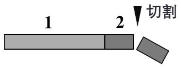
[0024] The optical fiber 1 is an ordinary single-mode optical fiber with a diameter of 125 μm and a core diameter of 9 μm; the optical fiber miniature self-focusing lens 2 is made by cutting a graded-index multimode optical fiber, the diameter of the graded-index multimode optical fiber ...


PUM

PropertyMeasurementUnit
diameteraaaaaaaaaa
diameteraaaaaaaaaa
diameteraaaaaaaaaa

Abstract

The invention provides a manufacturing method of a single-optical-fiber cascade type temperature-depth-salinity sensor for deep sea exploration. According to the single-optical-fiber cascade type temperature-depth-salinity sensor, three all-quartz sensing units are manufactured and cascaded on the same optical fiber by utilizing an electric arc welding and hydrogen-oxygen catalytic bonding technology. Due to the introduction of a plurality of optical fiber micro self-focusing lenses, under the condition that the optical transmission of the cascaded FP interferometer is not influenced, the sensitivity and the resolution can be improved by greatly increasing the cavity length of the two cascaded FP so as to obtain better sensing performance. According to the invention, an integral all-quartz structure in a complex deep sea detection environment is realized, all sensing elements are cascaded on a single optical fiber, and the optical fiber sensor has the advantages of small size, compact structure, high pressure resistance, corrosion resistance, suitability for long-distance measurement and the like, is simple in manufacturing process, good in repeatability and easy to manufacture and mass-produce, and is expected to become a candidate for deep sea exploration and research in the future.

Description

technical field [0001] The invention belongs to the technical field of optical fiber sensing, and relates to a method for manufacturing a single optical fiber cascaded temperature-depth-salinity sensor for deep sea surveying. Background technique [0002] Temperature, depth and salinity are important parameters required for ocean exploration and monitoring, and are of great significance to the research of oceanography, hydrometeorology, navigation and ecological balance. Currently, commercial conductance-temperature-depth (CTD) detection systems have been widely used in the study of marine environments. However, the core of the CTD system mainly relies on electronic components, which are easily affected by electromagnetic noise and seawater corrosion, and have defects such as high maintenance costs and difficult long-distance transmission. In recent years, due to the special advantages of anti-electromagnetic interference, corrosion resistance, easy distribution, networking...

Claims


Application Information

Patent Timeline
Patent Type & Authority Applications(China)
IPC IPC(8): G01D5/353
CPCG01D5/35312
Inventor 荆振国彭伟刘悦莹李昂刘强
Owner DALIAN UNIV OF TECH
Learn More