Glass fiber yarn auxiliary winding device
A winding device and technology of glass fiber yarn, which are applied in the directions of transportation and packaging, transportation of filamentous materials, and thin material processing, etc. The effect of uniform winding of yarn and prevention of falling
- Summary
- Abstract
- Description
- Claims
- Application Information
AI Technical Summary
Problems solved by technology
Method used
Image
Examples
Embodiment 1
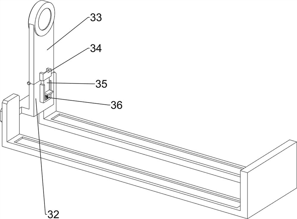
[0030] Such as figure 1 and figure 2 As shown, a glass fiber yarn auxiliary winding device includes a bottom plate 1, a first bearing seat 2, a first sliding sleeve 3, a first rotating shaft 4, a rotating motor 5, a first belt transmission device 6, a moving mechanism 7 and Clamping mechanism 8, the left side of the base plate 1 is provided with a first bearing seat 2, the first bearing seat 2 is provided with a first sliding sleeve 3, the first sliding sleeve 3 is rotatably provided with a first rotating shaft 4, and the left side of the base plate 1 A rotary motor 5 is provided, and a first belt transmission device 6 is arranged between the output shaft of the rotary motor 5 and the left end of the first rotating shaft 4. The first belt transmission device 6 is composed of two pulleys and a flat belt. The output of the rotary motor 5 A pulley is arranged on the shaft, another pulley is arranged at the left end of the first rotating shaft 4, a flat belt structure is arrange...
Embodiment 2
[0033] Such as image 3 and Figure 4As shown, on the basis of Embodiment 1, the moving mechanism 7 includes a first guide rod 71, a first slider 72, a second bearing seat 73 and a second sliding sleeve 74, which are arranged symmetrically between the left and right sides of the bottom plate 1 There are first guide rods 71, and a first slide block 72 is slidably arranged between the two first guide rods 71. A second bearing seat 73 is provided on the first slide block 72, and a second bearing seat 73 is provided on the second bearing seat 73. The sliding sleeve 74 and the second sliding sleeve 74 are slidingly matched with the first rotating shaft 4 .
[0034] After the glass fiber yarn winding is completed, the staff closes the rotating motor 5, and the rotating motor 5 stops rotating. The first rotating shaft 4 is driven by the first belt transmission device 6 to stop rotating on the first sliding sleeve 3. The staff passes through the clamping mechanism 8 The first rotati...
Embodiment 3
[0038] Such as Figure 5 , Figure 6 , Figure 7 , Figure 8 and Figure 9 As shown, it also includes a straight chute plate 9, a third slide block 10 and a wire block 11, the rear side of the base plate 1 is provided with a straight chute plate 9, and the straight chute plate 9 is slidably provided with a third slide block 10, A wire block 11 is arranged on the third slider 10 .
[0039] When it is necessary to wind the glass fiber yarn, the staff inserts the sleeve for winding the glass fiber yarn onto the first rotating shaft 4, and then clamps the first rotating shaft 4 through the limit rod 83, at this time the staff Pass one end of the glass fiber yarn that needs to be wound on the sleeve through the winding wire block 11, and when the first rotating shaft 4 rotates to drive the sleeve to rotate for winding, the staff pushes the third slider 10 on the straight chute plate 9 left and right Sliding, the third slider 10 slides left and right to drive the wire block 11 ...
PUM
 Abstract
Description
Claims
Application Information
 - R&D
- Intellectual Property
- Life Sciences
- Materials
- Tech Scout
- Unparalleled Data Quality
- Higher Quality Content
- 60% Fewer Hallucinations
Browse by: Latest US Patents, China's latest patents, Technical Efficacy Thesaurus, Application Domain, Technology Topic, Popular Technical Reports.
© 2025 PatSnap. All rights reserved.Legal|Privacy policy|Modern Slavery Act Transparency Statement|Sitemap|About US| Contact US: help@patsnap.com


