Multi-section three-parallel mechanism type mechanical arm device capable of achieving automatic folding and unfolding
An automatic retractable, robotic arm technology, applied in the field of robotic arms, can solve the problems of slow movement and inability to provide, and achieve the effect of ensuring rapidity
- Summary
- Abstract
- Description
- Claims
- Application Information
AI Technical Summary
Problems solved by technology
Method used
Image
Examples
specific Embodiment approach 1
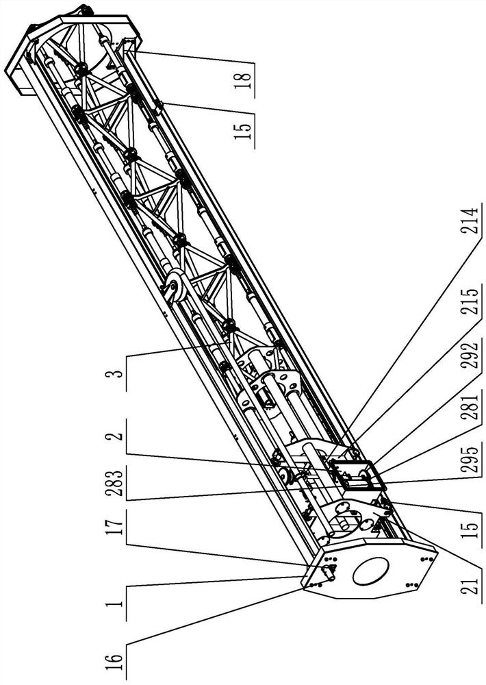
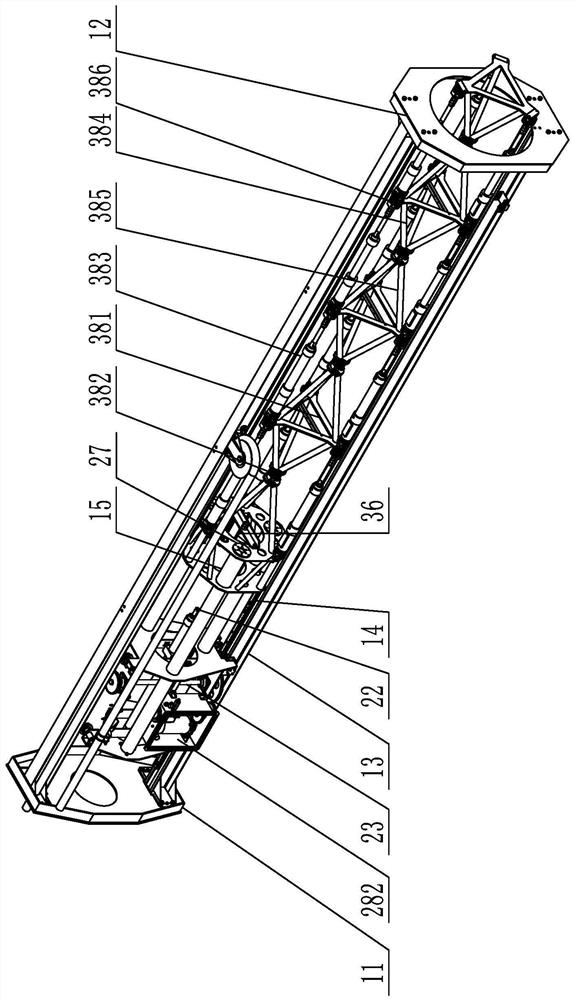
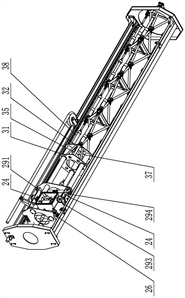
[0024] Specific implementation mode one: combine Figure 1 to Figure 4Describe this embodiment, a multi-section three-parallel mechanical arm device that can realize automatic retraction in this embodiment, it includes a fixed frame 1, a power cabin 2 and a main body of the mechanical arm 3, and the fixed frame 1 includes a tail support Seat 11, front support 12, two guide rails 13 and two tooth racks 14, front support 12 and tail support 11 are relatively horizontally arranged from top to bottom, and two guide rails 13 are relatively vertically arranged on the front support respectively. Between the seat 12 and the tail support 11, and the upper and lower ends of the guide rail 13 are respectively connected with the front support 12 and the inner wall of the tail support 11, and the inner walls of the guide rail 13 on both sides are parallel to the direction of the guide rail 13. A rack 14, the center of the front support 12 is provided with a hole through which the mechanica...
specific Embodiment approach 2
[0027] Specific implementation mode two: combination Figure 1 to Figure 4 To illustrate this embodiment, the fixed frame 1 of this embodiment also includes two limit switches 15, and a guide rail 13 in the fixed frame 1 is provided with two ends of the side walls near the front support 12 and the tail support 11 Two limit switches 15.
[0028] With such an arrangement, the relative position of the power cabin 2 on the guide rails 13 on both sides can be recorded, and cross-border can be prevented. Other compositions and connections are the same as in the first embodiment.
specific Embodiment approach 3
[0029] Specific implementation mode three: combination Figure 1 to Figure 4 To illustrate this embodiment, the fixed frame 1 of this embodiment also includes a hydraulic oil pipe 16 and an oil pipe positioning member 17. The oil pipe positioning member 17 is installed on the outer wall of the tail support 11, and the oil pipe assembly hole is provided on the tail support 11. The hydraulic oil pipe 16 One end passes through the tail support 11 , and the hydraulic oil pipe 16 extends to the outside of the tail support 11 and is connected with the oil pipe positioning member 17 .
[0030] In this way, the oil pipe positioning part 17 is installed on the outer side of the tail support 11 to fix the hydraulic oil pipe 16. The hydraulic oil pipe 16 provides the source power for the whole mechanism. The center of the front support 12 is provided with a hole through which the mechanical arm passes through, which is convenient for the main body of the mechanical arm. 3 stretches out, ...
PUM
 Abstract
Description
Claims
Application Information
 - Generate Ideas
- Intellectual Property
- Life Sciences
- Materials
- Tech Scout
- Unparalleled Data Quality
- Higher Quality Content
- 60% Fewer Hallucinations
Browse by: Latest US Patents, China's latest patents, Technical Efficacy Thesaurus, Application Domain, Technology Topic, Popular Technical Reports.
© 2025 PatSnap. All rights reserved.Legal|Privacy policy|Modern Slavery Act Transparency Statement|Sitemap|About US| Contact US: help@patsnap.com


