
An intelligent vision correction system

A vision correction and intelligent technology, applied in the field of vision correction, can solve the problems of sticking stains on the installation board, easy blocking of the baffle, offset, etc., to achieve the effect of avoiding sticking stains, ensuring accuracy, and ensuring cleanliness

Active Publication Date: 2022-06-24
杭州轻派科技有限公司
View PDF6 Cites 0 Cited by
  • Summary
  • Abstract
  • Description
  • Claims
  • Application Information

AI Technical Summary

Problems solved by technology

[0006] The purpose of the present invention is to provide an intelligent vision correction system to solve the problems in the background technology mentioned above. In the prior art, a baffle is usually used to block one eye for a monocular vision test when performing a vision test. The boards are held by the inspectors for inspection, which makes the baffle shift when it is easy to cover, resulting in the baffle not being able to completely cover one eye, making the single-eye detection results inaccurate and affecting the detection results.
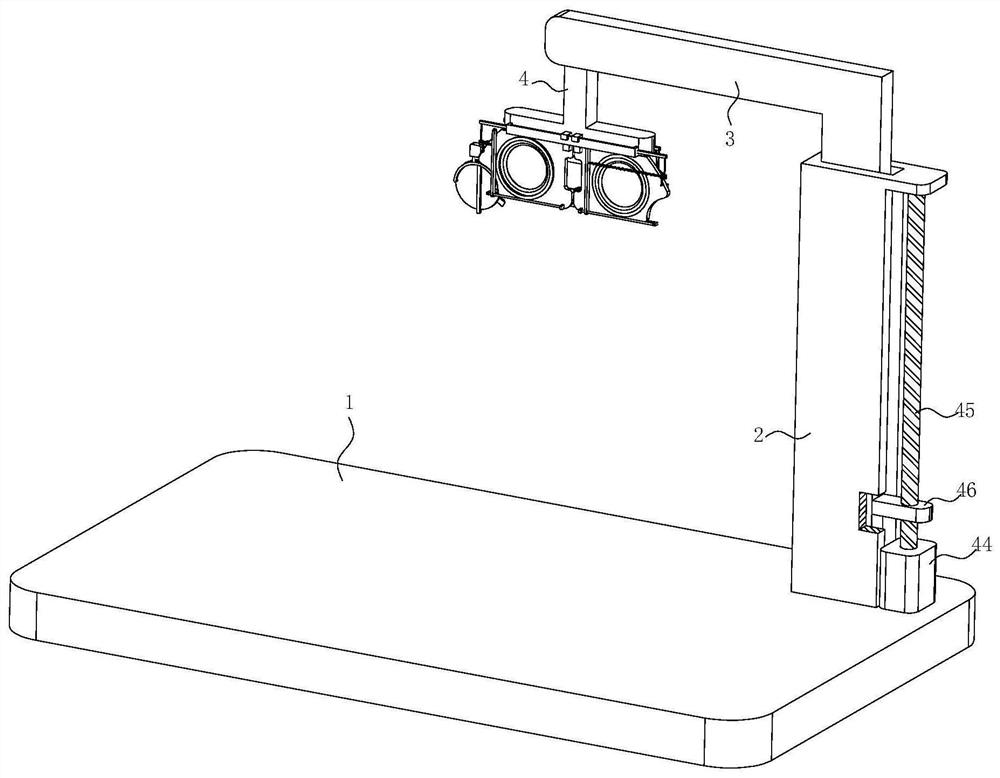
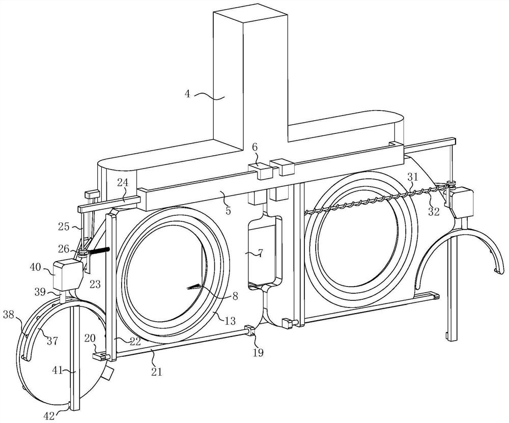
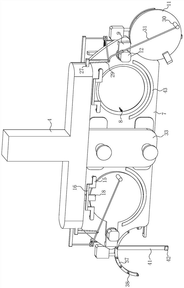
[0009] When working, because in the prior art, a baffle is usually used to block one eye for a monocular vision test when performing a visual inspection, but the baffle is held by the inspector for inspection each time, so that when the baffle is easily blocked, the Offset, the baffle cannot completely cover one eye, making the detection result of the single eye inaccurate and affecting the detection result. The present invention provides a technical solution to solve the above problems. When the present invention is used, the two baffles are in the near To detect the state of through-hole shielding, the person to be detected steps on the top of the bottom plate, adjust the driving mechanism so that the L-shaped lifting plate, T-shaped fixed plate and installation plate are within the eye range of the inspector, and cooperate with the person to carry out simple movement, so that the waiting The human eyes of the person to be detected are in the position facing the two detection through holes, and the two baffle plates and the mounting plate completely shield the person to be detected, so as to avoid the interference of the other eye during the single-eye detection, and then start the visual inspection For detection, start the first motor on one side first, and the first motor drives the first rotating rod and the shielding plate to rotate, so that the shielding plate slowly breaks away from the shielding detection through hole. During the rotation of the shielding plate, it drives the first guide block fixedly connected with it Rotate at the same time, so that the first guide block is slowly separated from the push plate, and the push plate, the first slide bar and the arc-shaped protective plate slowly slide forward under the pull of the first spring, so that the arc-shaped protective plate protrudes from the mounting plate, avoiding waiting The face of the inspected personnel is completely attached to the front surface of the mounting plate, as far as possible to ensure that the personnel are not in contact with the mounting plate, to ensure the cleanliness of the mounting plate, to avoid stains on the mounting plate after repeated use, and during the rotation of the shielding plate, The blocking plate pulls the pull rope through the fixed column. After the pull rope is guided by the U-shaped guide frame and the first guide wheel, it pulls the cleaning scraper. When the arc-shaped protective plate is used, the arc-shaped protective plate cannot protrude from the mounting plate, and the plane formed by the arc-shaped protective plate and the mounting plate is in full contact with the cleaning scraper. During the rotation of the shielding plate, the cleaning scraper is pulled by the pull cord to the outside of the mounting plate Move, scrape and clean the arc-shaped protective plate and the installation plate once, the L-shaped blocking plate hinders the second spring, and compress the second spring during the movement of the cleaning scraper to the outside, cleaning the bottom of the scraper and the installation plate at the same time position, so that the cleaning scraper moves close to the front surface of the installation plate under the pull of the pull rope. Break away from the pushing plate, when the cleaning scraper breaks away from the arc protection, the pushing plate, the first slide bar and the arc protection plate slowly slide forward under the pull of the first spring, so that the arc protection plate protrudes from the installation plate, avoiding The face of the person to be detected is completely attached to the front surface of the mounting plate. Try to ensure that the personnel do not touch the mounting plate, keep the mounting plate clean, and avoid stains on the mounting plate after multiple uses. However, after the detection of one eye is completed , the first motor starts to reverse, so that the blocking plate is slowly reset, and the pull rope is released, but at this time, the cleaning scraper is blocked by the arc protective plate and cannot be reset. When the blocking plate is completely reset, the first guide block on the blocking Press the pushing plate so that the pushing plate, the first sliding rod and the arc-shaped protective plate are retracted into the mounting plate again, and then, under the action of the second spring, the cleaning scraper moves to the inner side of the mounting plate along the polished rod and the mounting plate, In the same way, the other eye detection is carried out, so that each time a person needs to be tested for vision, the installation plate and the shielding plate are used to completely cover the eyes of the person with the detection, so as to avoid the phenomenon of incomplete occlusion during single-eye detection and ensure The accuracy of single-eye detection, and during detection, when the shielding plate is rotated, the cleaning scraper can clean the installation plate and the arc-shaped protective plate in advance before the detection, so as to avoid the stains left by the previous detection personnel from interfering with the detection, and After the cleaning scraper is cleaned, make the arc-shaped protective plate protrude from the mounting plate to prevent the face of the person to be detected from completely fitting on the front surface of the mounting plate, as far as possible to ensure that the personnel do not touch the mounting plate, ensure the cleanliness of the mounting plate, and avoid After repeated use, the mounting plate will adhere to stains, which is beneficial for personnel to perform visual inspection

Method used


Image

  • An intelligent vision correction system
  • An intelligent vision correction system
  • An intelligent vision correction system

Examples


Embodiment Construction

[0029] The technical solutions in the embodiments of the present invention will be clearly and completely described below with reference to the accompanying drawings in the embodiments of the present invention. Obviously, the described embodiments are only a part of the embodiments of the present invention, rather than all the embodiments. Based on the embodiments of the present invention, all other embodiments obtained by those of ordinary skill in the art without creative efforts shall fall within the protection scope of the present invention.

[0030] see Figure 1-8 , The present invention provides a technical solution: an intelligent vision correction system, comprising a backing plate 1, a U-shaped fixing sleeve 2 is fixedly connected to the top of the backing plate 1, and an L-shaped lifting plate 3 is slidably connected inside the U-shaped fixing sleeve 2. A drive mechanism for driving the L-shaped lifting plate 3 to move up and down is connected on the right side wall...


PUM


Abstract

The invention discloses an intelligent vision correction system in the technical field of vision correction, comprising a backing plate, a U-shaped fixing sleeve is fixedly connected to the top of the backing plate, and an L-shaped lifting plate is slidably connected inside the U-shaped fixing sleeve; the present invention By using the installation plate and the baffle plate to completely cover the eyes of the person with the tester every time the person needs to be tested for vision, avoiding the phenomenon of incomplete occlusion during the single-eye test, when the test is performed, the baffle plate is used to rotate to make the cleaning scraper Clean the mounting plate and the arc-shaped protective plate in advance before the inspection, to avoid the stains left by the personnel of the last inspection from interfering with the detection, and after the cleaning scraper is cleaned, make the arc-shaped protective plate protrude from the installation plate to avoid the The face of the personnel is completely attached to the front surface of the mounting plate, so as to ensure that the personnel are not in contact with the mounting plate as much as possible, and avoid stains on the mounting plate after repeated use, which is conducive to the visual inspection of personnel.

Description

technical field [0001] The invention relates to the technical field of vision correction, in particular to an intelligent vision correction system. Background technique [0002] The traditional eye examination is to use an eye examination chart. The examiner indicates the letter E on the eye chart, and the examinee makes gestures according to the opening direction of the letter E seen. The inspector determines the subject's vision according to the opening direction of the letter E and the direction of the gesture. [0003] The prior art discloses some invention patents on vision correction. The Chinese patent with the patent application number CN201811076298.9 discloses an intelligent vision detection and training correction system based on cloud computing. The system includes an identity verification module, a detection Information display module, logical judgment module and cloud data management module; this system is based on cloud computing technology, and uses identity...

Claims


Application Information

Patent Timeline
Patent Type & Authority Patents(China)
IPC IPC(8): A61B3/032B08B1/00B08B3/02B08B3/08B08B13/00
CPCA61B3/032A61B3/0016B08B3/02B08B3/08B08B13/00B08B1/165B08B1/30
Inventor 蔡景友刘宏图曹田
Owner 杭州轻派科技有限公司
Learn More