
Eyesight testing device

A vision detection and eye technology, which is applied in the direction of eye testing equipment, medical science, diagnosis, etc., can solve the problems of eye chart damage and difficult adjustment, and achieve the effect of easy use and vision detection

Inactive Publication Date: 2021-03-09
刘焕伟
View PDF0 Cites 6 Cited by
  • Summary
  • Abstract
  • Description
  • Claims
  • Application Information

AI Technical Summary

Problems solved by technology

[0003] The existing eye chart detection devices are all fixed structures, which are difficult to adjust, and after a long time of use, the eye chart will have a lot of dust attached to its surface, which needs to be cleaned manually in time, and manual cleaning is easy to cause damage to the eye chart

Method used


Image

  • Eyesight testing device
  • Eyesight testing device
  • Eyesight testing device

Examples


Embodiment 1

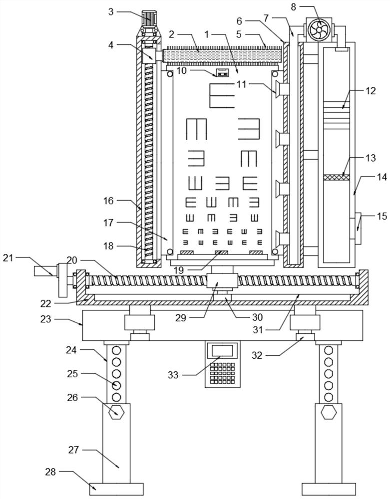
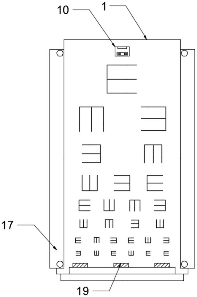
[0021] see Figure 1-2 , a kind of eyesight detection device, comprises vision detection table 1 and adjusting box 22, described vision detection table 1 left side is provided with lifting box 16, and screw rod one 18 is set in described lifting box body 16, and described screw rod one 18 and The inner wall of the lifting box 16 is rotationally connected, the surface of the screw rod-18 is provided with a nut-4, and the nut-4 can move up and down in the vertical direction with the rotation of the screw rod-18, and the upper surface of the top wall of the lifting box body 16 is provided with a nut-4. Drive motor 3, described drive motor 3 is fixedly connected with lifting box body 16 top walls, and described drive motor 3 output end passes through lifting box body 16 and is fixedly connected with screw rod one 18, and described nut one 4 is connected with rotating roller by connecting rod 2 rotating connection, the surface of the rotating roller 2 is equidistantly provided with...

Embodiment 2

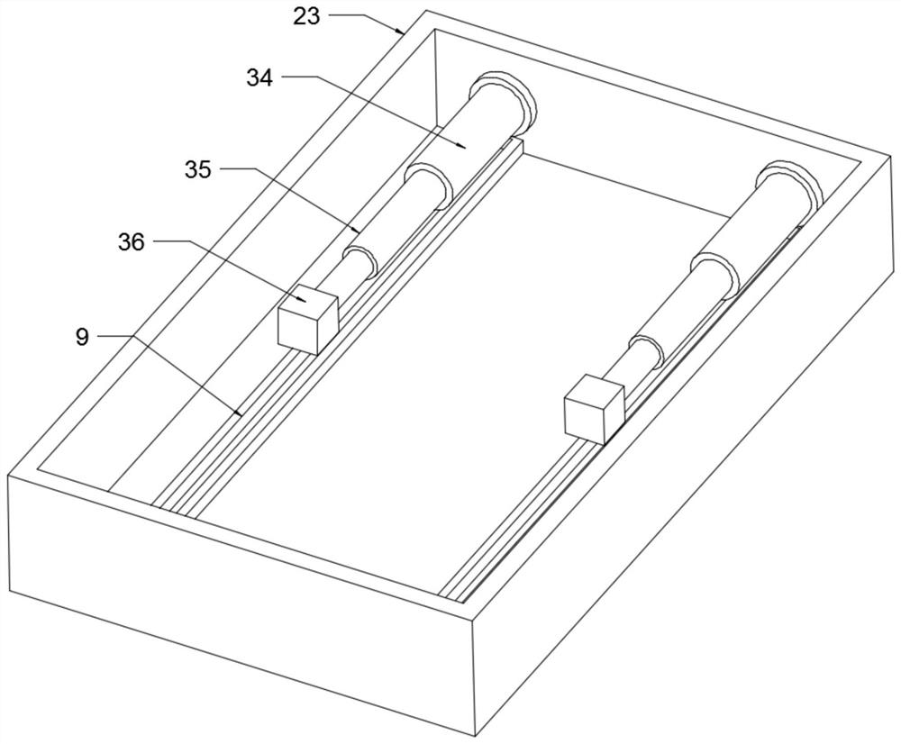
[0027] see Figure 1-3 , on the basis of Embodiment 1, in order to adjust the position of the visual acuity test meter 1, screw rod 2 20 is set in the described adjustment box 22, and described screw rod 2 20 is connected with the inner wall of adjustment box 22 by rotation, and the surface of the described screw rod 2 20 is Nut 2 29 is set, and described nut 2 29 can move left and right in the horizontal direction along with the rotation of screw rod 2 20. The left end of the screw rod 20 passes through the adjustment box 22 to extend and fix the connection handle 21. The bottom of the visual acuity test table 1 is fixedly connected, and by turning the handle 21, the handle 21 drives the screw rod 220 to rotate, and the nut two 29 drives the visual acuity test table 1 to move left and right in the horizontal direction to adjust its horizontal position. 22, a drive box 23 is arranged below, and a hydraulic cylinder 34 is arranged symmetrically in the drive box 23, and the hydr...


PUM


Abstract

The invention discloses an eyesight testing device, and relates to the technical field of eyesight testing auxiliary equipment. The eyesight testing device comprises an eyesight testing table and an adjusting box; the left side of the eyesight testing table is provided with a lifting box body; a screw rod I is arranged in the lifting box body; the surface of the screw rod I is provided with and anut I; the nut I is rotatably connected with a rotating roller; the right side of the eyesight testing table is provided with a supporting box body; and a dust collector is arranged above the supporting box body. The nut I drives the rotating roller and a cleaning hairbrush to do reciprocating motion on the surface of the eyesight testing table to clean dust on the surface of the eyesight testingtable; the dust collector sucks the dust on the surface of the eyesight testing table into a filtering box for filtering; a nut II drives the eyesight testing table to move leftwards and rightwards inthe horizontal direction to adjust the position of the eyesight testing table in the horizontal direction; telescopic rods pushes movable seats and the adjusting box to move horizontally to adjust the distance between the eyesight testing table and eyesight tested person, so that eyesight testing is facilitated, dust on the surface of the eyesight testing table does not need to be cleaned manually, and the eyesight testing device is more convenient to use.

Description

technical field [0001] The invention relates to the technical field of vision detection auxiliary equipment, in particular to an eye vision detection device. Background technique [0002] The eye chart used in medical testing mainly checks the central vision, that is, the central visual acuity of the macular area of ​​the retina, so that the preliminary situation of visual function can be easily and quickly understood, which is of great significance to the clinical diagnosis and treatment of eye diseases. It is designed according to the principle of viewing angle. The viewing angle is the angle formed by the light emitted by two external points and the node inside the eye. [0003] The existing eye chart detection devices are all fixed structures, which are difficult to adjust. After a long period of use, the eye chart will have a lot of dust attached to its surface, which needs to be cleaned manually in time. Manual cleaning is easy to cause damage to the eye chart. Conte...

Claims


Application Information

Patent Timeline
Patent Type & Authority Applications(China)
IPC IPC(8): A61B3/032B08B1/00B08B1/04B08B13/00
CPCA61B3/032B08B13/00B08B1/12B08B1/32
Inventor 刘焕伟
Owner 刘焕伟
Learn More