Light condenser, vehicle headlamp module, vehicle lamp and vehicle

A technology for concentrators and vehicles, which is applied in the direction of headlights, road vehicles, vehicle parts, etc. It can solve the problems of wear at the contact point of the low-beam concentrator, insufficient light efficiency, and limited center brightness, etc., to reduce the overall volume and installation accuracy requirements, improving light extraction efficiency, and reducing the installation structure

Pending Publication Date: 2021-08-20
HASCO VISION TECHNOLOGY CO LTD
View PDF2 Cites 0 Cited by
  • Summary
  • Abstract
  • Description
  • Claims
  • Application Information

AI Technical Summary

Problems solved by technology

[0003] Most of the existing technologies use light concentrators to guide, collimate and adjust the light emitted by multiple light sources to form a light shape with required performance. For example, the Chinese invention patent application with the application publication number CN109611780A discloses a vehicle lighting A light concentrator for a device, the light concentrator includes a plurality of collimator units, the light-incoming end of each collimator unit is in the shape of a paraboloid concave in the middle, and the light-emitting ends of each collimator unit are connected to each other or integrally formed It is the light exit end surface, which is a curved surface that gradually bends inward from top to bottom; the central illumination intensity of the light shape formed by the above technical solution is not high enough, because the light incident ends of the concentrator are arranged along the left and right directions, and the light source The emitted light is emitted forward through the concentrator, and the formed light shape is spliced ​​by the respective light shapes corresponding to the corresponding positions of the light incident ends and the light source. The improvement of the light intensity in the center of the light shape is achieved through the The light incident end is rotated to the middle, and the alignment is improved, but the central brightness of the light shape formed by this left and right splicing is still limited
For this reason, the Chinese utility model patent with the notification number CN210373264U discloses another light concentrator, which is also made of a material as a whole, and at least a pair of light concentrator elements are arranged up and down and share an optical channel. If the optical axis of one of the condensing elements coincides with the optical axis of the lens, its light can basically exit from the designated area of ​​the light exit surface of the light channel and project to the center area of ​​the light shape through the lens, while the optical axis of the other condensing element is opposite to the lens The optical axis is inclined. Since the light-transmitting part is made of the same material, only part of the light is emitted from the designated area of ​​the light-emitting surface, and other light is emitted from areas other than the designated area. The light effect is not high enough.
In addition, in the prior art, the lower boundary of the front end of the low beam concentrator in the far and near beam integrated car light module is used to form the upper boundary of the low beam light shape, and the upper boundary of the front end of the high beam concentrator is used to form the high beam light shape. The lower boundary, the low beam and the high beam are connected through the above two boundaries. There is no overlapping transition in this connection, and there will be a dark area at the junction, so that the connection between the high beam and the low beam is not good enough
Moreover, due to the contact between the front end of the low beam concentrator and the high beam concentrator, when vibration occurs, the front contact of the low beam concentrator and / or the high beam concentrator will wear, or even powder, so that the low beam The beam shape and / or high beam beam shape is affected, or even fails, that is, the beam shape changes to a level that does not meet the regulatory requirements

Method used


Image

  • Light condenser, vehicle headlamp module, vehicle lamp and vehicle
  • Light condenser, vehicle headlamp module, vehicle lamp and vehicle
  • Light condenser, vehicle headlamp module, vehicle lamp and vehicle

Examples


Embodiment Construction

[0057] Specific embodiments of the present invention will be described in detail below in conjunction with the accompanying drawings. It should be understood that the specific embodiments described here are only used to illustrate and explain the present invention, and are not intended to limit the present invention.

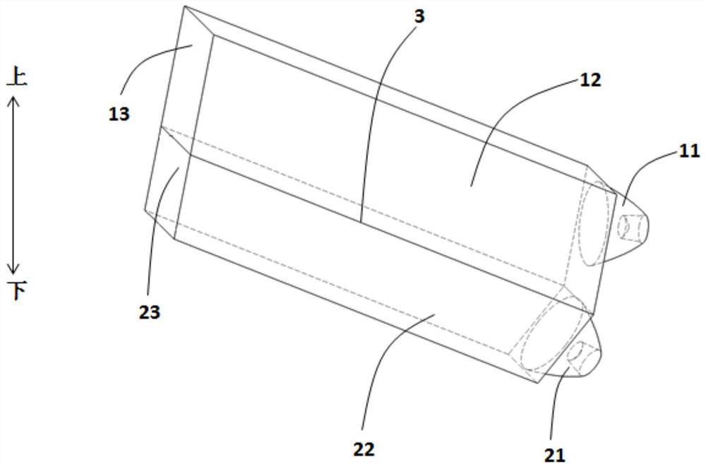
[0058] First of all, it should be noted that some orientation words involved in the following description to clearly illustrate the technical solution of the present invention, such as "up", "down", "front", "rear", etc. The meaning of the position analogy, for example, the roof is up, the position opposite to the roof is down, the front is front, and the rear is rear. It is only for the convenience of describing the present invention and simplifying the description, but does not indicate or imply that the device or element referred to must have a specific orientation, be constructed and operated in a specific orientation, and thus should not be construed as lim...


PUM


Abstract

The invention discloses a light condenser, a vehicle headlamp module, a vehicle lamp and a vehicle, the light condenser comprises a first light condensing unit and a second light condensing unit, the first light condensing unit comprises a first light incident part and a first light passing part, and the second light condensing unit comprises a second light incident part and a second light passing part; an interface is formed between the first light passing part and the second light passing part, the refractive index of the first light passing part is smaller than that of the second light passing part, and the emergent light of the first light incident part enters the first light passing part; at least part of the light can be refracted through the interface to enter the second light passing part and is emitted from a second front end face, and the emergent light of the second light incident part can be emitted from the second front end face after entering the second light passing part. According to the invention, at least part of the emergent light of the first light incident part and the emergent light of the second light incident part can be emitted to a designated area, so that the light loss is effectively reduced, and the light emitting efficiency is improved.

Description

technical field [0001] The invention relates to a vehicle headlight lighting device, in particular to a concentrator. In addition, the invention also relates to a vehicle headlamp module, a vehicle lamp and a vehicle. Background technique [0002] At present, in the lighting devices of the headlights of automobiles and other vehicles, more and more light-concentrating elements made of transparent materials are used to guide, collimate and adjust the light shape of the light emitted by the light source. Generally speaking, the lighting device with the above-mentioned light concentrating elements can be used to form all or part of the light shape of the low beam, high beam, etc. of the vehicle headlights. [0003] Most of the existing technologies use light concentrators to guide, collimate and adjust the light emitted by multiple light sources to form a light shape with required performance. For example, the Chinese invention patent application with the application publicati...

Claims


Application Information

Patent Timeline
Patent Type & Authority Applications(China)
IPC IPC(8): F21S41/25F21W102/135F21W107/10
CPCF21S41/25F21W2102/135F21W2107/10
Inventor 仇智平祝贺严海月桑文慧
Owner HASCO VISION TECHNOLOGY CO LTD
Why Eureka
Try Eureka