Reinforcing mesh assembling device and reinforcing mesh cage assembling method

An assembly method and networking technology, applied in auxiliary molding equipment, ceramic molding machines, manufacturing tools, etc., can solve the problems of reducing the production efficiency of autoclaved aerated concrete panels, reducing the networking efficiency, etc., to improve the connection efficiency, improve the The effect of networking efficiency

Active Publication Date: 2021-08-20
GUANGDONG BOZHILIN ROBOT CO LTD
View PDF5 Cites 0 Cited by
  • Summary
  • Abstract
  • Description
  • Claims
  • Application Information

AI Technical Summary

Problems solved by technology

[0003] In the prior art, a single piece of steel mesh is combined into a steel mesh cage after being connected by a buckle structure. This networking method is generally completed manually and requires the cooperation of multiple people, thereby reducing the cost of a single piece of steel mesh. The combination of sheet and buckle structure becomes the networking efficiency of reinforced mesh cage, which in turn reduces the production efficiency of the entire autoclaved aerated concrete slab

Method used


Image

  • Reinforcing mesh assembling device and reinforcing mesh cage assembling method
  • Reinforcing mesh assembling device and reinforcing mesh cage assembling method
  • Reinforcing mesh assembling device and reinforcing mesh cage assembling method

Examples


Embodiment 1

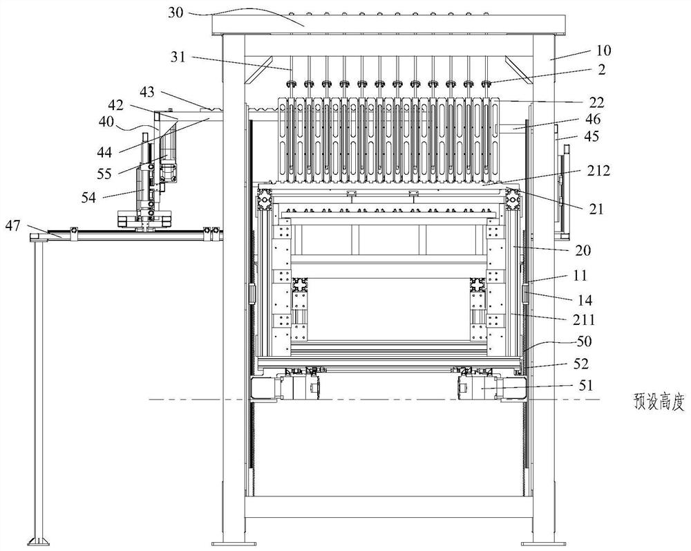
[0042] Such as figure 1 As shown, Embodiment 1 of the present invention provides a networking device. The networking device is used for assembling the mesh 1 and the buckle structure 2 , and the networking device includes a mesh lifting mechanism 50 , a mesh supporting structure 20 and a first cantilever structure 40 . Wherein, the mesh supporting structure 20 is arranged on the mesh lifting mechanism 50, and the mesh supporting structure 20 is used to accommodate a plurality of meshes 1 arranged in sequence; at least part of the mesh lifting mechanism 50 is movably arranged in the vertical direction, so as to Drive the mesh support structure 20 and the mesh 1 on the mesh support structure 20 to move synchronously, the first cantilever structure 40 is located on one side of the mesh lifting mechanism 50, the first cantilever structure 40 includes the first cantilever part 42, the first cantilever structure 40 The cantilever portion 42 is movably arranged in the vertical direc...

Embodiment 2

[0108] The difference from Example 1 is that, if Figure 10 As shown, in the second embodiment of the present invention, the first cantilever structure 40 includes two first cantilever portions 42 with a preset distance. Likewise, the second cantilever structure 45 includes two second cantilever portions 46 with a preset distance, and the second cantilever portions 46 are used to support the first cantilever portion 42 to prevent deformation of the first cantilever portion 42 to ensure better The longitudinal ribs of the ground support mesh.

[0109] It should be noted that the setting of the preset distance needs to ensure that the two first cantilever portions 42 can simultaneously correspond to the outermost longitudinal ribs (ie, the uppermost longitudinal ribs and the lowermost longitudinal ribs) of the supporting mesh. For example, the preset distance can be set to be equal to the vertical distance between the outermost longitudinal ribs of the mesh. In this way, by pro...

Embodiment 3

[0112] The difference from Example 1 is that, if Figure 11 As shown, the networking device includes two first cantilever structures 40 and two second cantilever structures 45 corresponding to the two first cantilever structures 40, and the two first cantilever structures 40 can be separated from each other to separate the mesh The uppermost longitudinal reinforcement and the lowermost longitudinal reinforcement are used for support.

[0113] In this way, two second drive structures 55 also need to be provided, so that the two first cantilever structures 40 can be driven away from each other, so that the mesh can be snapped into the upper buckle structure and the lower buckle structure respectively. , to complete the automatic networking process.

[0114] Other structures in the third embodiment are the same as those in the first embodiment, and will not be repeated here.


PUM


Abstract

The invention provides a reinforcing mesh assembling device and a reinforcing mesh cage assembling method. The reinforcing mesh assembling device comprises a mesh supporting structure which is arranged on a mesh lifting mechanism, and used for accommodating a plurality of meshes arranged in sequence; the mesh lifting mechanism, wherein at least part of the mesh lifting mechanism is movably arranged in the vertical direction so as to drive the mesh supporting structure and the meshes located on the mesh supporting structure to move synchronously; and a first cantilever structure which is located on one side of the mesh lifting mechanism and comprises a first cantilever part, wherein the first cantilever part is movably arranged in the vertical direction and the first direction so that at least part of the first cantilever part can be arranged in the meshes in a penetrating mode and support longitudinal bars of at least one pair of meshes at a constant interval, under the driving of the first cantilever part, the longitudinal ribs of the at least one pair of meshes can move to preset positions of buckle structures in the vertical direction, and the at least one pair of meshes are clamped with the buckle structures. According to the technical scheme, the reinforcing mesh assembling device can improve the assembling efficiency of the reinforcing meshes and the buckle structures.

Description

technical field [0001] The invention relates to the field of steel mesh cage forming, in particular to a netting device and a method for assembling the steel mesh cage. Background technique [0002] In the production process of autoclaved aerated concrete slabs, it is necessary to add steel mesh cages in the slabs to enhance its structural stability, that is, after combining a single piece of steel mesh and a buckle structure to form a steel mesh cage, then the steel mesh cage Hang on the steel braze and insert into the pouring formwork box. [0003] In the prior art, a single piece of steel mesh is combined into a steel mesh cage after being connected by a buckle structure. This networking method is generally completed manually and requires the cooperation of multiple people, thereby reducing the cost of a single piece of steel mesh. The combination of sheet and buckle structure becomes the networking efficiency of the reinforced mesh cage, which in turn reduces the produc...

Claims


Application Information

Patent Timeline
IPC IPC(8): B28B23/02B28B17/00
CPCB28B23/02B28B17/00
Inventor 邬全兵李小龙张琼
Owner GUANGDONG BOZHILIN ROBOT CO LTD
Why Eureka
Try Eureka