Eureka AIR delivers breakthrough ideas for toughest innovation challenges, trusted by R&D personnel around the world.

A sterile laminar flow chamber for patients with aplastic anemia

An aplastic and anemic technology, applied in treatment rooms, life-saving equipment, separation methods, etc., can solve the problems of reduced system maintenance efficiency, complicated replacement and maintenance operations, and time-consuming replacement of filters, so as to reduce labor load and improve The effect of replacement maintenance efficiency

Active Publication Date: 2022-04-12
JILIN UNIV
View PDF12 Cites 0 Cited by
  • Summary
  • Abstract
  • Description
  • Claims
  • Application Information

AI Technical Summary

Problems solved by technology

[0003] However, the air filtration system of the existing aseptic room needs regular inspection, repair and maintenance, and the filter screen should be cleaned in time. It takes a lot of time to filter the net, reducing the maintenance efficiency of the system

Method used


Image

  • A sterile laminar flow chamber for patients with aplastic anemia
  • A sterile laminar flow chamber for patients with aplastic anemia
  • A sterile laminar flow chamber for patients with aplastic anemia

Examples


Embodiment 1

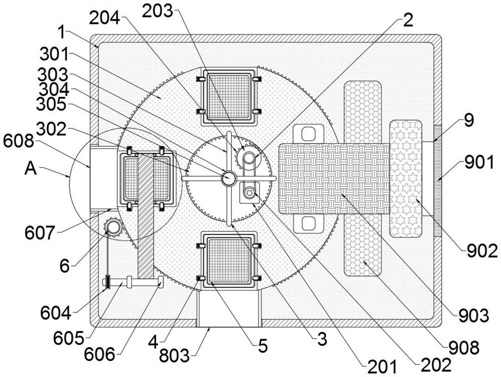
[0028] Example 1: Please refer to figure 1 , 3And 4, a sterile laminar flow chamber for patients with aplastic anemia, including an installation frame 1 installed on the top of the laminar flow chamber, a drive mechanism 2 is installed on the left side of the installation frame 1, and the drive mechanism 2 is connected to the turntable mechanism 3, and the turntable mechanism 3 The installation mechanism 4 is evenly distributed on the top, the filter mechanism 5 is installed on the installation mechanism 4, and the unloading mechanism 6 is installed on the left side of the turntable mechanism 3. The unloading mechanism 6 includes a driven gear 601, and the driven gear 601 is connected with the turntable mechanism 3. , the first winding roller 602 is installed on the driven gear 601, the first winding roller 602 is connected with the second winding roller 604 through the connecting cable 603, the second winding roller 604 is fixedly installed on the rotating rod 605, and the ro...

Embodiment 2

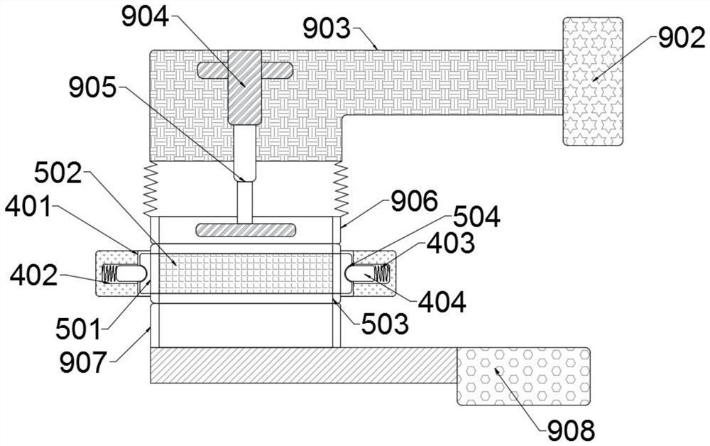
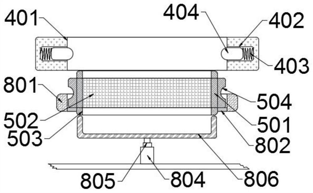
[0033] Example 2: Please refer to Figure 1-4 , a sterile laminar flow chamber for patients with aplastic anemia, comprising an installation frame 1 installed on the top of the laminar flow chamber, a drive mechanism 2 is installed on the left side of the installation frame 1, the drive mechanism 2 is connected to a turntable mechanism 3, and the turntable mechanism 3 is evenly Installing mechanism 4 is distributed, and filtering mechanism 5 is installed on installing mechanism 4, and unloading mechanism 6 is installed on the left side of turntable mechanism 3, and unloading mechanism 6 comprises driven gear 601, and driven gear 601 is connected with turntable mechanism 3 transmission, from The first winding roller 602 is installed on the moving gear 601, the first winding roller 602 is connected to the second winding roller 604 by the connecting cable 603, the second winding roller 604 is fixedly installed on the rotating rod 605, and the rotating rod 605 is installed On the ...


PUM


Abstract

The invention relates to the technical field of aseptic laminar flow chambers, and discloses a sterile laminar flow chamber for patients with aplastic anemia, which includes an installation frame installed on the top of the laminar flow chamber, and a driving mechanism is installed on the left side of the installation frame. The mechanism is connected with the turntable mechanism, the installation mechanism is evenly distributed on the turntable mechanism, the filter mechanism is installed on the installation mechanism, and the unloading mechanism is installed on the left side of the turntable mechanism. The first winding roller is installed on the moving gear, and the first winding roller is connected to the second winding roller through a connecting cable. The second winding roller is fixedly installed on the rotating rod, and the rotating rod is installed on the spring shaft. A percussion mechanism is connected, a feeding mechanism is installed on the front side of the turntable mechanism, and a ventilation mechanism is installed on the right side of the turntable mechanism. The invention facilitates the replacement and loading and unloading operations of the filter frame of the filter mechanism, improves the replacement efficiency of the filter frame, reduces the labor load of workers, and has strong practicability.

Description

technical field [0001] The invention relates to the technical field of a sterile laminar flow chamber, in particular to a sterile laminar flow chamber for patients with aplastic anemia. Background technique [0002] Patients with aplastic anemia need to recuperate in a sterile room, and the existing single-person sterile laminar flow room is filtered through a high-efficiency air filtration system to achieve a sterile environment, creating a fresh, clean, comfortable, and low-bacteria space. Environment, so that patients suffer as little damage as possible during recuperation, and greatly reduce the secondary infection rate of patients and medical staff; [0003] However, the air filtration system of the existing aseptic room needs regular inspection, repair and maintenance, and the filter screen should be cleaned in time. It takes a lot of time to filter the net, reducing the maintenance efficiency of the system. [0004] In view of the above problems, the present inventi...

Claims


Application Information

Patent Timeline
Patent Type & Authority Patents(China)
IPC IPC(8): A61G10/00B01D46/88B01D46/10
CPCA61G10/005B01D46/10B01D46/88
Inventor 王佳欢王旭
Owner JILIN UNIV
Why Eureka
Eureka Blog
Learn More