
Distributed photovoltaic optimal configuration method based on two-stage planning

A distributed photovoltaic and optimized configuration technology, applied in the direction of photovoltaic power generation, circuit devices, power network operating system integration, etc., can solve problems such as node voltage exceeding the limit, unreasonable distribution network loss, and affecting the operation of the distribution network. To achieve the effect of increasing node voltage, improving absorption capacity, and simple and easy solution process

Inactive Publication Date: 2021-08-17
YUNNAN POWER GRID CO LTD ELECTRIC POWER RES INST
View PDF2 Cites 2 Cited by
  • Summary
  • Abstract
  • Description
  • Claims
  • Application Information

AI Technical Summary

Problems solved by technology

However, the unreasonable configuration of a large number of distributed photovoltaics will cause many problems such as increased network losses of the distribution network and node voltage over-limits, which will affect the safe and stable operation of the distribution network.

Method used


Image

  • Distributed photovoltaic optimal configuration method based on two-stage planning
  • Distributed photovoltaic optimal configuration method based on two-stage planning
  • Distributed photovoltaic optimal configuration method based on two-stage planning

Examples


Embodiment Construction

[0108] The embodiments will be described in detail hereinafter, examples of which are illustrated in the accompanying drawings. When the following description refers to the accompanying drawings, the same numerals in different drawings refer to the same or similar elements unless otherwise indicated. The implementations described in the following examples do not represent all implementations consistent with this application. These are merely examples of systems and methods consistent with aspects of the present application as recited in the claims.

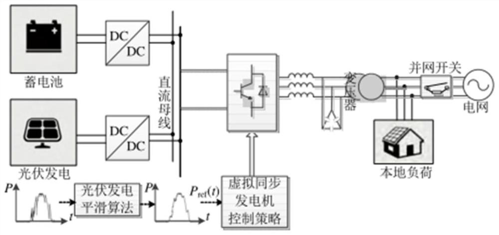
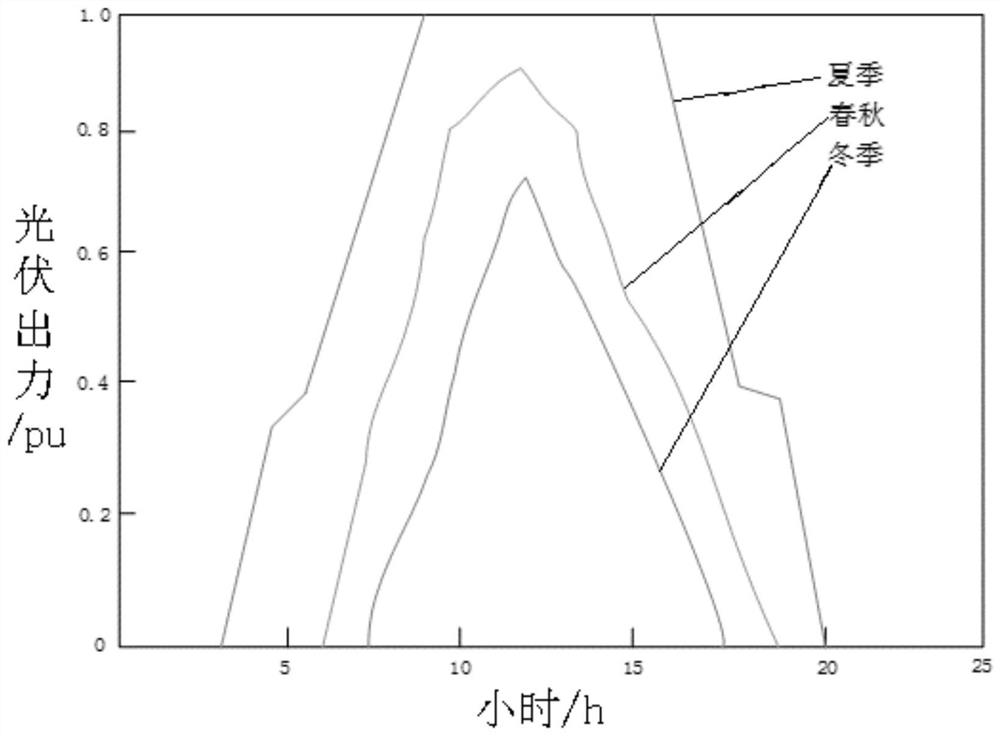
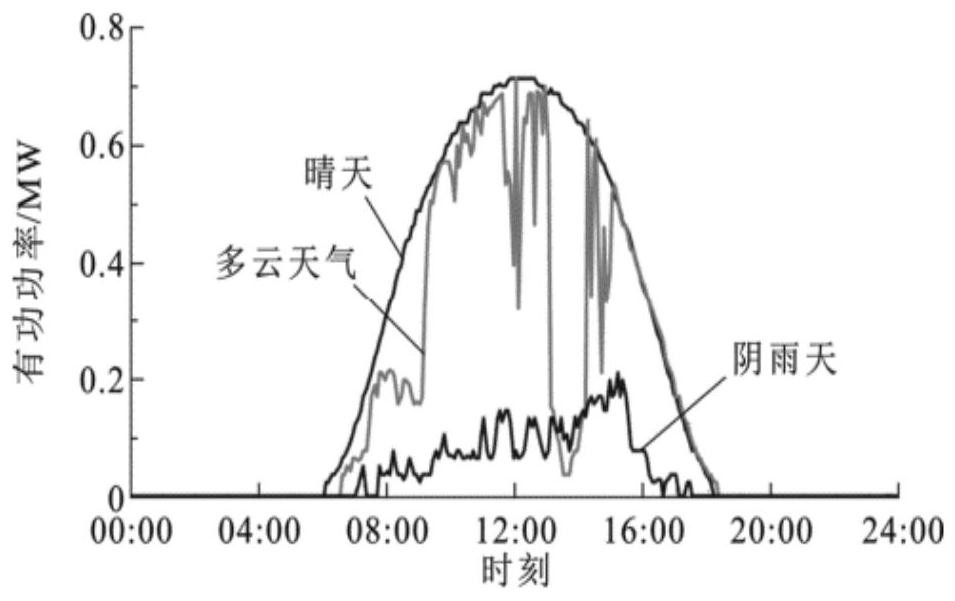
[0109] see figure 1 , is a schematic diagram of the optical storage distributed power system structure; figure 2 is the typical daily output curve of photovoltaics throughout the year; image 3 is the daily output curve of photovoltaic power generation under different typical weather; Figure 4 The scene reduction flow chart provided by the embodiment of this application; Figure 5 Gray wolf algorithm flow chart provided for...


PUM


Abstract

A distributed photovoltaic optimal configuration method based on two-stage planning comprises the following steps of firstly, establishing a photovoltaic power generation random output model, and then implementing the operations at the following two stages that at the first stage, the network loss sensitivity variance of each node in a power distribution network is calculated through a network loss sensitivity variance method; the network loss sensitivity variance values are compared and analyzed, the access sequence of the distributed photovoltaic at each node is judged, and the distributed photovoltaic capacity and an initial mounting position are calculated; and at the second stage, the distributed photovoltaic capacity and the initial mounting position serve as input of the second stage, a target function is established with the minimum annual investment and operation cost, the minimum voltage deviation and the minimum power distribution network loss generated after the distributed photovoltaic is connected into the power distribution network as targets, and finally an optimal configuration scheme is obtained. The configuration scheme obtained through the method can stabilize the photovoltaic output power fluctuation and improve the photovoltaic permeability and utilization rate and the absorption capacity of photovoltaic power generation.

Description

technical field [0001] This application relates to the field of new energy grid-connected technologies, and in particular to a distributed photovoltaic optimal configuration method based on two-stage planning. Background technique [0002] Nowadays, the traditional electric power industry is facing huge environmental protection pressure. Under the trend of sustainable development of new energy, distributed power generation technology is more and more widely used. However, the unreasonable configuration of a large number of distributed photovoltaics will cause many problems such as increased network losses of the distribution network and node voltage over-limits, which will affect the safe and stable operation of the distribution network. [0003] In the prior art, different objective functions are established according to the different impacts of distributed photovoltaics being connected to the distribution network. For example, take the minimum comprehensive cost as the ob...

Claims


Application Information

Patent Timeline
Patent Type & Authority Applications(China)
IPC IPC(8): H02J3/46H02J3/00H02J3/38
CPCH02J3/466H02J3/472H02J3/0075H02J3/381H02J2203/10H02J2203/20H02J2300/26H02J2310/64Y04S20/222Y02E10/56Y02B70/3225
Inventor 闫凯璐李胜男何廷一吴水军
Owner YUNNAN POWER GRID CO LTD ELECTRIC POWER RES INST
Learn More