Swivel type ratchet tightener

A wire tensioner and ratchet technology, applied in the direction of overhead line/cable equipment, adjusting/maintaining mechanical tension, etc., can solve the problems of troublesome handle operation, unfavorable use, and inability to accurately take up wires, so as to avoid loosening and benefit precision Better adjustment and take-up effect

Active Publication Date: 2021-08-17
SHANGHAI MUNICIPAL ELECTRIC POWER CO
View PDF11 Cites 3 Cited by
  • Summary
  • Abstract
  • Description
  • Claims
  • Application Information

AI Technical Summary

Problems solved by technology

[0003] 1. When tightening, it is necessary to turn the handle to drive the ratchet to rotate. First of all, the handle is intermittently rotated, and it is necessary to continuously perform actions similar to pressing down to drive the ratchet to rotate to realize the winding, so the operation through the handle is troublesome And it is not conducive to use on the erected wires, and there is a certain range of motion between the ratchet pawls when the wire is taken up, and the ratchet will drive the rotating shaft to rotate at a larger angle when it rotates, and it cannot be guaranteed to be just right. It is stuck on the pawl, making it impossible to take up the wire accurately;
[0004] 2. In the process of thread tightening, it cannot be guaranteed that the steel wire rope can be wound firmly every turn, and there will be multiple turns on the same part, and the number of turns in other parts is small, which is not conducive to the uniform winding of the memory, and it is not possible to Ensure the tension of the take-up line, which will easily cause the take-up reel to be messed up due to loose wire rope when it is under tension, which not only affects the effective use and service life of the wire rope, but also is not conducive to the conductor fast and accurate tensioning

Method used


Image

  • Swivel type ratchet tightener
  • Swivel type ratchet tightener
  • Swivel type ratchet tightener

Examples


Embodiment Construction

[0020] The following will clearly and completely describe the technical solutions in the embodiments of the present invention with reference to the accompanying drawings in the embodiments of the present invention. Obviously, the described embodiments are only some of the embodiments of the present invention, not all of them. Based on the embodiments of the present invention, all other embodiments obtained by persons of ordinary skill in the art without making creative efforts belong to the protection scope of the present invention.

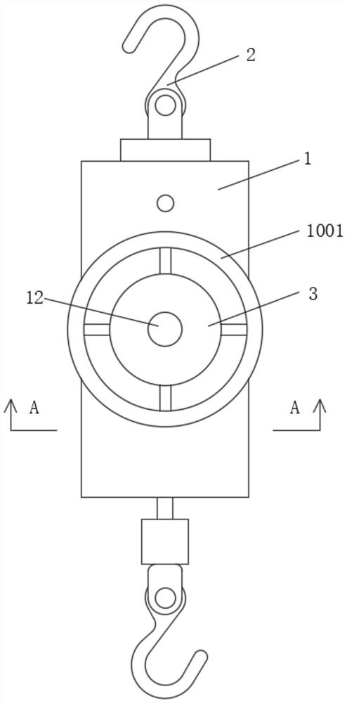
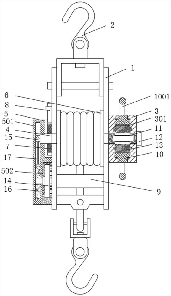
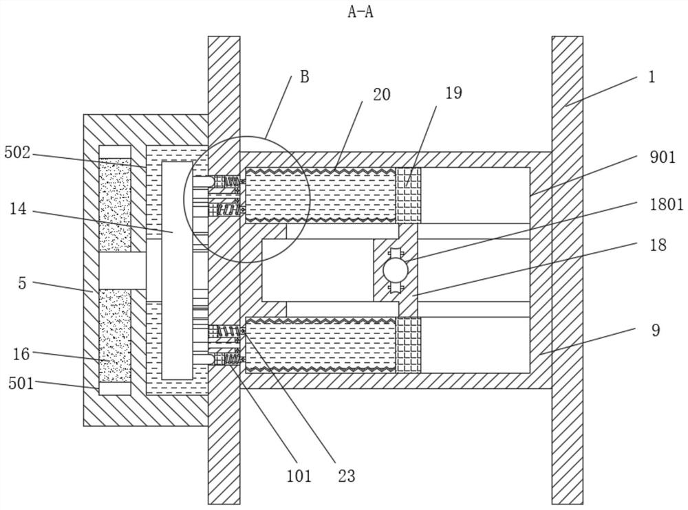
[0021] see Figure 1-6 , a swivel type ratchet wire tensioner, comprising a support frame 1, the top and bottom of the support frame 1 are respectively movably connected with hooks 2, one side of the support frame 1 is fixedly equipped with a rotating box 3, and the other side of the support frame 1 A transmission box 5 is fixedly installed, and a rotating shaft 4 passing through the support frame 1 is movably installed between the rotating box 3...


PUM


Abstract

The invention relates to the technical field of power systems, and discloses a swivel type ratchet tightener. A rotating box is fixedly mounted at one side of a supporting frame, a transmission box is fixedly mounted at the other side of the supporting frame, and a take-up wheel is fixedly mounted on an outer ring of the rotating shaft in the supporting frame; a wire guide block is fixedly mounted at the position, located at the bottom of the take-up wheel, in the supporting frame, the outer ring of a gear cavity is movably sleeved with a rotating disc, and a driving rotating sleeve fixedly connected with the rotating shaft is movably installed in the center of the gear cavity; a pressure adjusting screw rod is sleeved with a sleeve hole in a threaded manner, a hydraulic cavity is formed at the bottom in the transmission box, close to the inner side, and a rotating disc fixedly connected with a second transmission wheel is movably installed in the hydraulic cavity. The middle of the wire guide block is movably sleeved with a wire guide sliding block, and by means of the improvement of the rotating disc and the structural design and transmission design of the wire guide block, it is guaranteed that when the wire tightener is used, the usage precision can be guaranteed, and a wire tightening effect is better.

Description

technical field [0001] The invention relates to the technical field of power systems, in particular to a swivel-type ratchet wire tensioner. Background technique [0002] The wire tensioner is used to tighten the wire in the construction of overhead line laying. Its basic principle is to use two hooks to connect one end with the wire and fix the other end on the fixture, and tighten the wire rope by rotating the ratchet to connect the hook to the The wire is straightened, mainly through the cooperation of the ratchet and pawl to realize the function of winding. The structure is simple, but there are still certain problems in the use process: [0003] 1. When tightening, it is necessary to turn the handle to drive the ratchet to rotate. First of all, the handle is intermittently rotated, and it is necessary to continuously perform actions similar to pressing down to drive the ratchet to rotate to realize the winding, so the operation through the handle is troublesome And it ...

Claims


Application Information

Patent Timeline
IPC IPC(8): H02G1/04H02G7/02
CPCH02G1/04H02G7/02
Inventor 马宇璇
Owner SHANGHAI MUNICIPAL ELECTRIC POWER CO
Why Eureka
Try Eureka