Liquid cooling pump cavity flow channel structure and liquid cooling pump

A pump cavity and liquid cooling technology, applied in the field of liquid pumps, can solve the problems of limited application occasions, high energy consumption, large size, etc., and achieve the effects of favorable flow rate, improved work efficiency, and good diversion effect.

Pending Publication Date: 2021-08-17
HUANG TSUNG HSIEN YUAN SHAN HSIANG
View PDF0 Cites 0 Cited by
  • Summary
  • Abstract
  • Description
  • Claims
  • Application Information

AI Technical Summary

Problems solved by technology

The driving performance of the liquid pump directly affects the smoothness and flow rate of the liquid flow. In actual use, it is necessary to increase the impeller speed, increase the size of the entire liquid pump, etc. to select a liquid pump with larger working performance parameters to increase the flow rate. On the one hand, the cost is high, and the energy consumption is also large; on the other hand, the large size limits its application
Therefore, for situations where size requirements or / and power consumption requirements are high, conventional liquid pumps are limited in fluid flow smoothness and flow rate, making it difficult to meet higher performance requirements

Method used


Image

  • Liquid cooling pump cavity flow channel structure and liquid cooling pump
  • Liquid cooling pump cavity flow channel structure and liquid cooling pump
  • Liquid cooling pump cavity flow channel structure and liquid cooling pump

Examples


Embodiment Construction

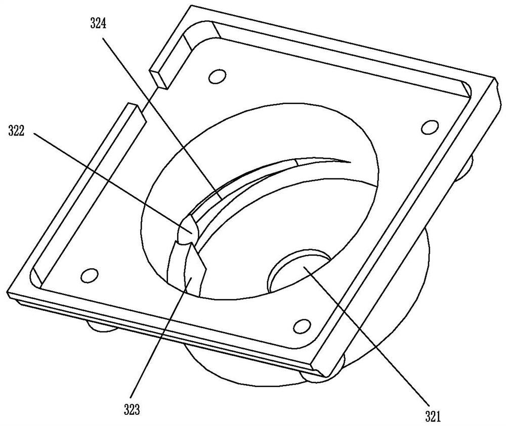
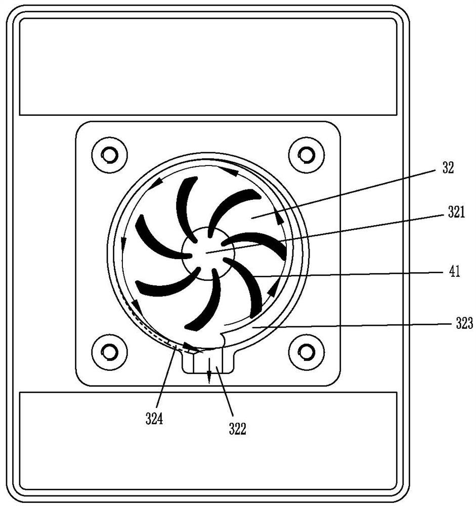
[0032] Please refer to Figure 1 to Figure 8 As shown, it shows the specific structure of the preferred embodiment of the present invention. .

[0033] A liquid-cooled pump chamber flow channel structure, including a liquid pump installation cavity 32, the bottom of the liquid pump installation cavity 32 is provided with a liquid inlet hole 321 in the center, and the circumferential side of the liquid pump installation cavity 32 is provided with a liquid outlet hole 322; on the side wall of the inner peripheral side wall of the liquid pump installation chamber 32 corresponding to the liquid outlet hole 322, a liquid blocking boss 323 is protruded, and the other side corresponding to the liquid outlet hole 322 is concavely provided with a guide groove 324; The rotation axis of the impeller 41 of the liquid pump is the front-rear direction, the liquid blocking boss 323 is arranged in a gradually thinning manner along the rotation circumference of the impeller 41, and the guide ...


PUM


Abstract

The invention discloses a liquid cooling pump cavity flow channel structure and a liquid cooling pump. The liquid cooling pump cavity flow channel structure comprises a liquid pump mounting cavity, a liquid inlet hole is formed in the center of the bottom of the liquid pump mounting cavity, and liquid outlet holes are formed in the circumferential side of the liquid pump mounting cavity. A liquid blocking boss is convexly arranged on one side, corresponding to the liquid outlet holes, of the inner peripheral side wall of the liquid pump mounting cavity, and a flow guide groove is concavely formed in the other side, corresponding to the liquid outlet holes, of the inner peripheral side wall of the liquid pump mounting cavity. The liquid blocking boss is arranged in the rotating circumferential direction of an impeller from thick to thin, and the flow guide groove is arranged in the rotating circumferential direction of the impeller from shallow to deep and penetrates through the liquid outlet holes. Therefore, a good flow guide effect is achieved, the smoothness is better, and the working efficiency of the liquid pump can be improved.

Description

technical field [0001] The present invention relates to the technology in the field of liquid pumps, in particular to a liquid-cooled pump chamber flow channel structure and a liquid-cooled pump, which are mainly but not limited to liquid-cooled pumps applied to radiators. Background technique [0002] The current liquid cooling radiator usually consists of a liquid cooling row and a liquid cooling head, and a liquid pump is used to drive the liquid cooling row and the liquid circulation in the liquid cooling head. After the liquid absorbs heat on the liquid cooling head, it enters the liquid cooling row to dissipate heat. , the cooled liquid returns to the liquid cooling head. The driving performance of the liquid pump directly affects the smoothness and flow rate of the liquid flow. In actual use, it is necessary to increase the impeller speed, increase the size of the entire liquid pump, etc. to select a liquid pump with larger working performance parameters to increase t...

Claims


Application Information

Patent Timeline
IPC IPC(8): F04D13/04H05K7/20
CPCH05K7/20218F04D13/04F04D29/426F04D29/428F04D1/00F05D2210/11F05D2240/12
Inventor 黄崇贤
Owner HUANG TSUNG HSIEN YUAN SHAN HSIANG
Why Eureka
Try Eureka