
Friction power generation device utilizing wave energy and offshore monitoring device with same

A technology of friction power generation and wave energy, applied in friction generators, circuit devices, ocean energy power generation, etc., can solve the problems of low power generation efficiency, difficult to collect, high cost, etc., to extend the service life, the design is simple and practical, and the installation is simple. Effect

Pending Publication Date: 2021-08-17
CHONGQING UNIV
View PDF8 Cites 2 Cited by
  • Summary
  • Abstract
  • Description
  • Claims
  • Application Information

AI Technical Summary

Problems solved by technology

In the early days, scientists in China and foreign countries have realized the huge energy of the ocean, but there has been no substantial breakthrough
Due to the irregularity of ocean wave motion, seawater corrosion, and wave beating, this energy is extremely difficult to collect.
At present, most of the power generation devices used to collect wave energy are electromagnetic power generation, and the cost is high
Most of the wave energy in the ocean belongs to low-frequency vibration, and the existing electromagnetic generators cannot collect this low-frequency vibration energy, which leads to low power generation efficiency

Method used


Image

  • Friction power generation device utilizing wave energy and offshore monitoring device with same
  • Friction power generation device utilizing wave energy and offshore monitoring device with same
  • Friction power generation device utilizing wave energy and offshore monitoring device with same

Examples


Embodiment Construction

[0043] Embodiments of the technical solutions of the present invention will be described in detail below in conjunction with the accompanying drawings. The following examples are only used to illustrate the technical solutions of the present invention more clearly, and therefore are only examples, rather than limiting the protection scope of the present invention.

[0044] It should be noted that, unless otherwise specified, the technical terms or scientific terms used in this application shall have the usual meanings understood by those skilled in the art to which the present invention belongs.

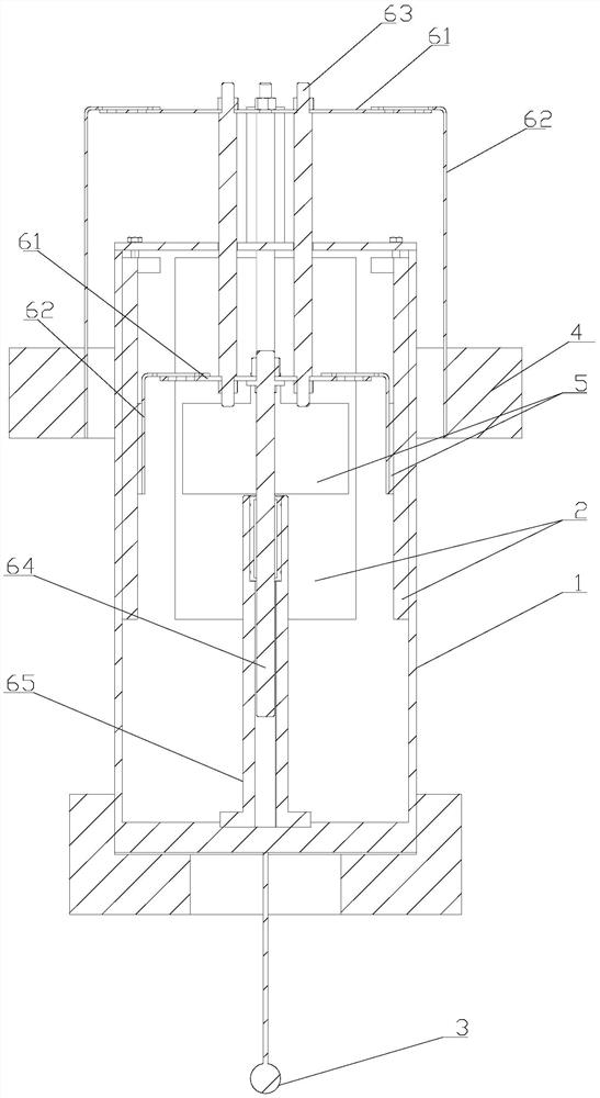
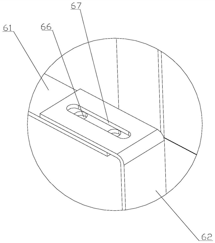
[0045] The invention provides a friction power generation device utilizing wave energy, such as Figure 1 to Figure 2 As shown, it includes a casing 1, a fixed friction plate 2, a bottom weight 3, a floating object 4, a sliding friction plate 5 and a transmission device, wherein: the casing 1 is a hollow structure; the fixed friction plate 2 is fixed on the inner wall of the casing 1...


PUM


Abstract

The invention discloses a friction power generation device utilizing wave energy and an offshore monitoring device with the same. The friction power generation device comprises a shell, a fixed friction plate, a bottom weight, a floating object, a sliding friction plate and a transmission device, wherein the shell is of a hollow structure, the fixed friction plate is fixedly arranged on the inner side wall of the shell, a sliding type friction generator is arranged on the face away from the inner side wall of the shell, the bottom weight goes deep into the sea surface and is connected with the shell, the floating object is arranged on the outer side of the shell, suspends on the water surface and moves up and down along with waves, the sliding friction plate is arranged in the shell and is in sliding connection with the fixed friction plate, a first end of the transmission device is connected with the sliding friction plate, a second end of the transmission device extends out of the shell to be connected with the floating object, a first end and a second end of a transmission rotating shaft synchronously move, wave energy is efficiently collected and converted into electric energy, and therefore, the friction power generation device is reasonable in structural arrangement, easy to install and convenient to use.

Description

technical field [0001] The invention relates to the technical field of wave energy power generation, in particular to a friction power generation device utilizing wave energy and an offshore monitoring device equipped with the device. Background technique [0002] my country has a vast coastline and ocean wave energy and ocean current energy have high energy density and a wide range of energy sources. The development of blue energy has become the top priority for solving energy problems. In the early days, Chinese and foreign scientists have realized the huge energy of the ocean, but there has been no substantial breakthrough. Due to the irregularity of ocean wave motion, seawater corrosion, and wave beating, this energy is extremely difficult to collect. At present, most of the power generation devices used to collect wave energy are electromagnetic power generation, and the cost is high. Most of the wave energy in the ocean is low-frequency vibration, and the existing el...

Claims


Application Information

Patent Timeline
IPC IPC(8): F03B13/18H02N1/04H02S10/10H02S10/20H02J7/32H02J7/35G01D21/00
CPCF03B13/1845H02N1/04H02S10/10H02S10/20H02J7/32H02J7/345H02J7/35G01D21/00Y02E70/30Y02E10/30Y02E10/50
Inventor 艾斌孙嘉琛李大林朱恺李鑫常秋翔方圆
Owner CHONGQING UNIV
Learn More