
Improved shear wall formwork reinforcing method

A formwork reinforcement and shear wall technology, which is applied in the direction of formwork/formwork/work frame, connection parts of formwork/formwork/work frame, and on-site preparation of building components, which can solve the inconvenience of shear wall formwork reinforcement. , Unfavorable recycling of turnover materials, affecting the quality of concrete molding, etc., to achieve the effect of reducing screw holes through the wall, quality assurance, and reducing engineering costs

Inactive Publication Date: 2021-08-17
MCC5 GROUP CORP SHANGHAI
View PDF5 Cites 0 Cited by
  • Summary
  • Abstract
  • Description
  • Claims
  • Application Information

AI Technical Summary

Problems solved by technology

[0003] However, the traditional reinforcement method is not conducive to the recycling of turnover materials, especially the sub-fluted wood and glued wood panels. After repeated use, they basically lack edges and corners, and the moment of inertia decreases. They are later used as waste wood fuel, and the initial investment cost is high.
At the same time, the entire 900mm×1830mm panel is mostly screw holes through the wall, which affects the quality of subsequent concrete molding
[0004] Therefore, there are above-mentioned inconveniences and problems in the known shear wall formwork reinforcement method

Method used


Image

  • Improved shear wall formwork reinforcing method
  • Improved shear wall formwork reinforcing method
  • Improved shear wall formwork reinforcing method

Examples


Embodiment 1

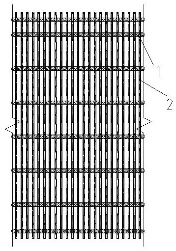
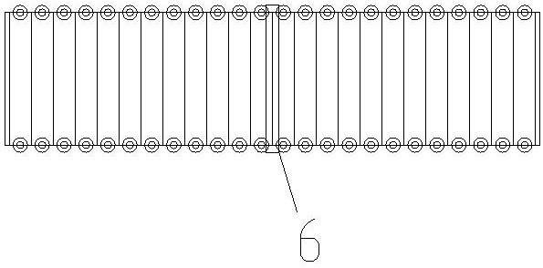
[0028] see now Figure 1-3 , the improved shear wall formwork reinforcement method of the present invention, its reinforcement system is mainly made up of laminated wood plywood panel 5, steel pipe secondary corrugation 2, steel pipe main corrugation 3, pull screw 1, and seam beam 6.

[0029] Specifications of materials used:

[0030] 1) Laminated wood plywood panel: length × width = 1830mm × 900mm, panel thickness 15mm.

[0031] 2) Steel pipe secondary flute, steel pipe main flute: diameter x wall thickness = 48mm x 3.0mm, length 6m.

[0032] 3) Pulling screw: the diameter is not less than 16mm, and it is fastened with a mountain-shaped butterfly buckle 4.

[0033] 4) Patchwork wooden frame: thickness×width=40mm×90mm, length 3000mm.

[0034] The specific operation of the improved shear wall formwork reinforcement method of the present invention: the reinforcement method is applicable to a shear wall height not greater than 6m, and a shear wall thickness not greater than 50...


PUM

PropertyMeasurementUnit
heightaaaaaaaaaa
thicknessaaaaaaaaaa
diameteraaaaaaaaaa

Abstract

The invention discloses an improved shear wall formwork reinforcing method. The improved shear wall formwork reinforcing method is suitable for a shear wall with the height not larger than 6 m and the thickness not larger than 500 mm and is characterized by comprising the following steps that a, composite wood plywood is transversely laid; b, the distance between secondary edges of vertical steel pipes is 150 mm; c, the reinforcing distance between secondary lower ends is 700 mm; and d, the middle reinforcing distance takes the width of the composite wood plywood as the boundary, wherein a splicing seam of the laminated wood plywood is sealed by a wood brace of 40mm * 90mm * 3000mm from bottom to top. The improved shear wall formwork reinforcing method has the advantages that the reinforcing structure is simple, operation is easy, the construction efficiency is improved, pull screws penetrate through the wall at an abutted seam of two panels, through-wall screw holes are reduced, the concrete forming quality and the risk of water seepage blocking of the screw holes in the later period are guaranteed, the quality is guaranteed, the effect is remarkable, and the engineering cost is reduced.

Description

technical field [0001] The invention relates to a method for supporting a shear wall formwork, in particular to an improved reinforcement method for a shear wall formwork. Background technique [0002] Reinforced concrete structure is the main structural form of modern buildings or structures. Among them, shear wall is commonly used, also known as wind-resistant wall and seismic wall. It mainly bears the horizontal load and vertical load caused by wind load or earthquake. Prevents structural shear damage. With the integral pouring of walls, columns, beams, and slabs, although the quality of the concrete structure is significantly improved, the reinforcement of the shear wall formwork is often not firm, and it is easy to expand, deform, and shift, resulting in irregular concrete molding. The traditional reinforcement is assembled with wooden molds (900mm×1830mm), the panel is made of 15mm thick wood plywood, the secondary corrugation is made of 40mm×90mm wooden beams, the sp...

Claims


Application Information

Patent Timeline
Patent Type & Authority Applications(China)
IPC IPC(8): E04G11/12E04G17/00E04G17/065
CPCE04G11/12E04G17/001E04G17/0657
Inventor 赵鹏飞
Owner MCC5 GROUP CORP SHANGHAI
Learn More