Laser cutting machine

A laser cutting machine and cutting mechanism technology, applied in laser welding equipment, welding/cutting auxiliary equipment, auxiliary devices, etc., can solve the problems affecting the subsequent use of products, positioning operations, poor material cutting accuracy, etc., to improve efficiency and quality, improved accuracy

Active Publication Date: 2021-08-17
艾博特镭射科技徐州有限公司
View PDF9 Cites 0 Cited by
  • Summary
  • Abstract
  • Description
  • Claims
  • Application Information

AI Technical Summary

Problems solved by technology

[0003] However, the current laser cutting machine has the following problems when cutting products: 1. The laser cutting machine in traditional industrial manufacturing cannot automatically position the material to be cut, and needs to manually move the material to carry out the cutting operation, making the material's The cutting accuracy is poor; 2. The existing laser cutting cannot cool the cut products in time. The waste heat of the laser will expand the cutting edge, and even produce unevenness, resulting in a low yield rate, and cannot be processed in time. The smoke and waste generated during cutting are cleaned up, which will affect the subsequent use of the product

Method used


Image

  • Laser cutting machine
  • Laser cutting machine
  • Laser cutting machine

Examples


Embodiment Construction

[0026] The embodiments of the present invention will be described in detail below with reference to the accompanying drawings, but the present invention can be implemented in many different ways defined and covered by the claims.

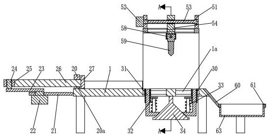
[0027] refer to figure 1 and figure 2 , a laser cutting machine, comprising a base plate 1, a feeding mechanism 2, a clamping mechanism 3, a dust suction mechanism 4, a cutting mechanism 5 and a cooling mechanism 6, the lower end of the right part of the base plate 1 is equipped with a clamping mechanism 3, the base plate 1 A cutting mechanism 5 is installed on the right part of the upper end, a dust suction mechanism 4 is installed on the cutting mechanism 5, a feeding mechanism 2 is installed on the left end of the base plate 1, and a cooling mechanism 6 is installed on the right end of the base plate 1.

[0028] refer to figure 2 and Figure 6, the feeding mechanism 2 includes a positioning plate 20, a straight plate 21, a No. 4 motor 22, a ...


PUM


Abstract

The invention relates to the technical field of cutting machines, in particular to a laser cutting machine. The laser cutting machine comprises a bottom plate, a feeding mechanism, a clamping mechanism, a dust collection mechanism, a cutting mechanism and a cooling mechanism, wherein the clamping mechanism is installed at the lower end of the right portion of the bottom plate; the cutting mechanism is installed on the right portion of the upper end of the bottom plate; the dust collection mechanism is installed on the cutting mechanism; the feeding mechanism is installed at the left end of the bottom plate; and the cooling mechanism is installed at the right end of the bottom plate. According to the laser cutting machine, the following problems existing when an existing laser cutting machine cuts a product are solved: I, the laser cutting machine in traditional industrial manufacturing cannot automatically position materials needing to be cut, and cutting operation can only be carried out by manually moving the materials, so that the cutting accuracy of the materials is poor; and II, a cut product cannot be cooled in time in existing laser cutting, and waste heat of laser can expand a cutting opening, so that the yield is low, and subsequent use of the product is affected.

Description

technical field [0001] The invention relates to the technical field of cutting machines, in particular to a laser cutting machine. Background technique [0002] The laser cutting machine focuses the laser light emitted from the laser device into a high power density laser beam through the optical path system. The laser beam irradiates the surface of the workpiece to make the workpiece reach the melting point or boiling point. At the same time, the high-pressure gas coaxial with the beam will blow away the molten or gasified metal. purpose of cutting. [0003] However, the current laser cutting machine has the following problems when cutting products: 1. The laser cutting machine in traditional industrial manufacturing cannot automatically position the material to be cut, and needs to manually move the material to carry out the cutting operation, making the material's The cutting accuracy is poor; 2. The existing laser cutting cannot cool the cut products in time. The waste...

Claims


Application Information

Patent Timeline
IPC IPC(8): B23K26/38B23K26/70B23K26/142B23K37/04B23K26/14B23K26/08
CPCB23K26/0869B23K26/14B23K26/38B23K37/04B23K26/142B23K26/702
Inventor 李未登
Owner 艾博特镭射科技徐州有限公司
Why Eureka
Try Eureka