
Fireproof and explosion-proof new energy automobile storage battery structure

A technology for new energy vehicles and batteries, applied in secondary batteries, structural parts, battery covers/end covers, etc., can solve problems affecting users' life and property safety, potential safety hazards, battery fires, etc., to reduce the chemical reaction rate, The effect of preventing fire and explosion, and preventing excessive temperature

Active Publication Date: 2021-08-13
北京智帮帮科技有限公司
View PDF6 Cites 4 Cited by
  • Summary
  • Abstract
  • Description
  • Claims
  • Application Information

AI Technical Summary

Problems solved by technology

[0003] However, the traditional battery only has a simple charge and discharge function, and the positive and negative poles are exposed to the air for a long time, so it is impossible to deal with the special conditions that occur when the battery is working, so that the battery is prone to fire or explosion due to the high temperature generated during its own work, and When the battery is working normally, the positive and negative poles may be short-circuited in contact with sewage, which also has potential safety hazards and seriously affects the safety of users' lives and property. Therefore, a fire-proof and explosion-proof new energy vehicle battery structure is proposed to solve the above problems.

Method used


Image

  • Fireproof and explosion-proof new energy automobile storage battery structure
  • Fireproof and explosion-proof new energy automobile storage battery structure
  • Fireproof and explosion-proof new energy automobile storage battery structure

Examples


Embodiment 1

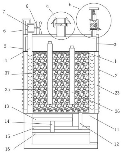
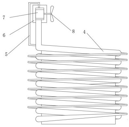
[0024] Embodiment 1: as figure 2 and Figure 6 As shown, when the new energy electric vehicle is running on the road, the fan blades are blown by the wind and start to rotate, the cooling liquid in the cooling pipe 5 is blown and cooled by the outside wind, and the right end of the first rotating shaft 8 is welded with 3-6 fan blades. blade, the blade rotates to rotate the first shaft 8, the first shaft 8 rotates the second gear 10 through the first gear 7, the first gear 7 meshes with the second gear 10, and the first gear 7 and the second gear 10 rotate through The cooling liquid in the cooling pipe 5 can be continuously pumped into the cooling pipe 4, so that the cooling liquid in the cooling pipe 4 absorbs the heat emitted by the battery and then flows into the cooling pipe 5 for air-cooling to cool down. The temperature is too high, resulting in damage to components and short circuits;

Embodiment 2

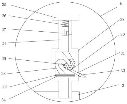
[0025] Embodiment 2: as figure 1 and Figure 5 As shown, when the gas in the protective cover 3 is affected by the heat of the battery, it will expand. The left side of the gas outlet pipe 17 is rotated and connected to the first column 19 that runs through and extends to the outside of the right side of the gas outlet pipe 17. The expanded gas continues to pass through the first column 19. The Z-shaped through hole of a cylinder 19 squeezes the first cylinder 19 to the left, and a Z-shaped vent hole is opened inside the first cylinder 19 until the expanded gas can pass through the Z-shaped through hole of the first cylinder 19 Discharge the protective cover 3 to prevent the positive pole 35 and negative pole 36 of the battery and the wires connected to them from being squeezed by high-pressure gas from being damaged and causing a short circuit. After the expanded high-temperature gas is discharged, the first spring 21 makes the first cylinder deform through elastic deformatio...

Embodiment 3

[0026] Embodiment 3: as figure 1 As shown, when the battery is overheated, the water in the second box 11 is heated and expands, and the top of the push rod 14 is welded with a first stopper 13, so that the first stopper 13 drives the piston 16 to move downward through the push rod 14 The top of the second box 11 is covered with an electrolyte tube 12 that runs through and extends to the bottom of the baffle 15, so that the electrolyte 37 in the battery flows into the sealed space formed by the piston 16 and the baffle 15 through the electrolyte tube 12, The chemical reaction rate in the battery is slowed down, and the overheated battery is prevented from being damaged and short-circuited to cause fire or explosion. After the battery cools down, the cooled and retracted water makes the piston 16 push the electrolyte 37 back into the battery case 1 through negative pressure. , to make the battery work normally;


PUM


Abstract

The invention discloses a fireproof and explosion-proof new energy automobile storage battery structure, and relates to the technical field of storage batteries. Aiming at the problems of fire or explosion and the like caused by short circuit of electronic components due to high temperature generated when a storage battery works and contact between positive and negative electrodes of the storage battery and an external object, the fireproof and explosion-proof new energy automobile storage battery structure comprises a battery shell. According to the fireproof and explosion-proof type new energy automobile storage battery structure, cooling liquid can be cooled through air cooling, then the storage battery is circularly cooled through the cooling liquid, the situation that the temperature of the storage battery is too high, components are damaged, and short circuit occurs is prevented, high-temperature and high-pressure gas generated when the storage battery works is exhausted, meanwhile, external sewage is prevented from entering, the storage battery can also absorb air to the outside to eliminate the negative pressure in the working environment and filter moisture in the air, and when the temperature of the storage battery is too high, electrolyte can be automatically extracted from the storage battery, the chemical reaction rate of the storage battery is reduced, and fire disasters and explosions caused by high temperature are prevented.

Description

technical field [0001] The invention relates to the technical field of batteries, in particular to a fireproof and explosion-proof new energy vehicle battery structure. Background technique [0002] Battery A battery is a device that directly converts chemical energy into electrical energy. It is a rechargeable battery designed to recharge through a reversible chemical reaction. It usually refers to a lead-acid battery. It is a type of battery and belongs to the secondary battery. Secondary battery, its working principle: when charging, the external electric energy is used to regenerate the internal active material, the electric energy is stored as chemical energy, and the chemical energy is converted into electric energy output again when it needs to be discharged, such as mobile phone batteries commonly used in life. [0003] However, the traditional battery only has a simple charge and discharge function, and the positive and negative poles are exposed to the air for a lo...

Claims


Application Information

Patent Timeline
IPC IPC(8): H01M10/613H01M10/625H01M10/6556H01M10/6563H01M10/6568H01M50/141H01M50/143H01M50/147H01M50/186H01M50/333H01M50/358H01M50/77H01M50/59H01M50/591B01D53/26
CPCB01D53/266H01M10/613H01M10/625H01M10/6556H01M10/6563H01M10/6568Y02E60/10
Inventor 何爱萍徐冰荷
Owner 北京智帮帮科技有限公司
Learn More