
Light source module and electronic device with light source module

A technology of a light source module and an electronic device, applied in the optical field, can solve the problems of light energy loss, uneven light mixing effect, inability to effectively miniaturize the light source module 1, etc.

Pending Publication Date: 2021-08-13
PRIMAX ELECTRONICS LTD
View PDF2 Cites 0 Cited by
  • Summary
  • Abstract
  • Description
  • Claims
  • Application Information

AI Technical Summary

Problems solved by technology

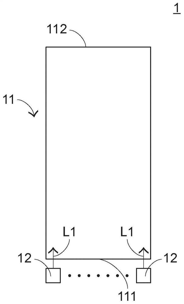
[0004] Generally speaking, the color uniformity of the light source provided by the light source module 1 is proportional to the length of the light mixing structure 11, that is, the longer the light mixing structure 11 is, the more uniform the color of the light source it outputs. The length of the optical structure 11 is too long, which not only easily causes the loss of light energy, but also makes the light source module 1 unable to be effectively miniaturized, and the electronic device that does not use the light source module 1 is developed towards the direction of lightness, thinness, and shortness; The shorter the length of the light structure 11, the more the volume of the light source module 1 can be reduced, but it will cause an uneven light mixing effect

Method used


Image

  • Light source module and electronic device with light source module
  • Light source module and electronic device with light source module
  • Light source module and electronic device with light source module

Examples


Embodiment Construction

[0063] Embodiments of the present invention will be further explained in conjunction with the accompanying drawings below. Wherever possible, in the drawings and description, the same reference numerals represent the same or similar components. In the drawings, the shape and thickness may be exaggerated for simplification and convenient labeling. It should be understood that elements not particularly shown in the drawings or described in the specification are forms known to those skilled in the art. Those skilled in the art can make various changes and modifications according to the content of the present invention.

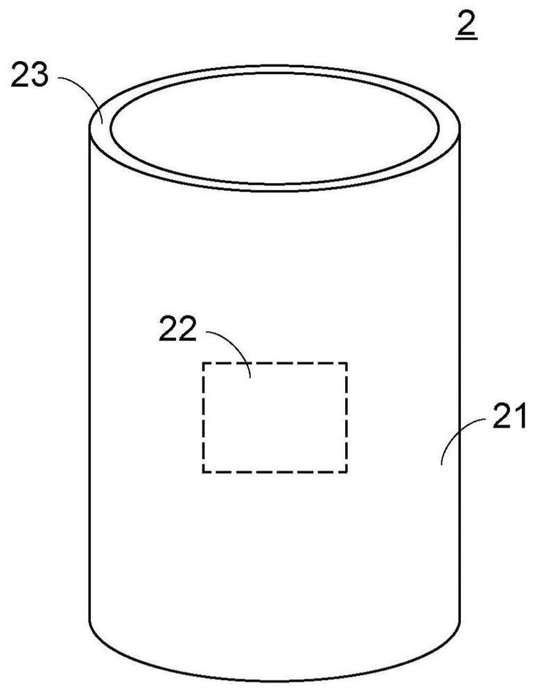
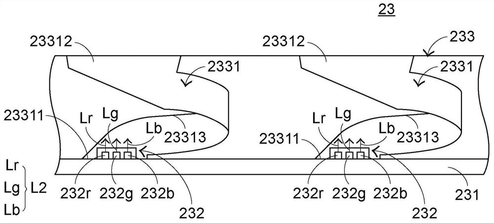
[0064] see Figure 2 ~ Figure 3 , figure 2 It is a schematic diagram of the structure concept of the electronic device of the present invention in a preferred embodiment, image 3 for figure 2 Conceptual schematic of the partial structure shown. The electronic device 2 includes a housing 21, a circuit module 22, and a light source module 23. The circuit m...


PUM


Abstract

The invention provides a light source module and an electronic device with the light source module. The light source module comprises a bearing substrate, a light emitting unit and a light mixing structure, wherein the light mixing structure is arranged on the bearing substrate and comprises a bent light mixing channel, and light beams provided by the light emitting unit are incident into the light mixing channel for light mixing, and the light is output after being mixed. In addition, the invention also provides an electronic device with the light source module.

Description

technical field [0001] The invention relates to the field of optics, in particular to a light source module and an electronic device with the light source module. Background technique [0002] With the evolution of the electronic industry and the vigorous development of industrial technology, various electronic devices are mostly developed and designed in the direction of lightness and portability, so that users can use them for mobile business or entertainment purposes anytime and anywhere. And because the integration and application of machine, light and electricity have been paid more and more attention in recent years, various light source modules are being widely extended to various products, such as the application of light source modules to audio systems that can play music Products (such as speakers), so that the audio products have a luminous effect. [0003] see figure 1 , which is a conceptual schematic diagram of an existing light source module. The light sour...

Claims


Application Information

Patent Timeline
Patent Type & Authority Applications(China)
IPC IPC(8): H01L25/075F21V7/04F21Y115/10
CPCH01L25/0753F21V7/04F21Y2115/10
Inventor 江湘湄黄韦强叶明辉
Owner PRIMAX ELECTRONICS LTD
Learn More