Light steel bar truss floor support plate

A technology for reinforced trusses and floor decks, which is applied to floors, structural elements, building components, etc. It can solve the problems of heavy weight of reinforced truss floor decks, easy sliding and dislocation, and insufficient adhesion, so as to reduce weight and increase stability Sexuality, the effect of reducing dosage

Pending Publication Date: 2021-08-13
江苏昊钢建筑科技有限公司
View PDF4 Cites 3 Cited by
  • Summary
  • Abstract
  • Description
  • Claims
  • Application Information

AI Technical Summary

Problems solved by technology

[0003] However, the steel plates used for the existing steel truss floor decks are mostly solid structures, which makes the overall weight of the steel bar truss floor decks relatively large, and the surface of the steel bar truss floor decks is mostly smooth, so that the grip between it and the concrete Not enough, the adhesion is not strong enough, and at the same time, the steel truss floor deck needs to be spliced ​​between the main bodies of multiple steel truss floor decks during installation. use, needs improvement

Method used


Image

  • Light steel bar truss floor support plate
  • Light steel bar truss floor support plate
  • Light steel bar truss floor support plate

Examples


Embodiment Construction

[0021] The technical solutions in the embodiments of the present invention will be apparent from the drawings in the embodiment of the present invention.

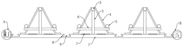
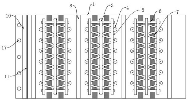
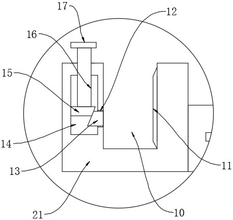
[0022] like Figure 1-5 As shown, the present invention provides a technical solution: a lightweight reinforced truss floor, including a bottom mold steel plate 1, a bottom mold steel plate 1 having a plurality of steel reinforcing components, a plurality of steel reinforcing components uniformly arranged in the bottom mold On the upper surface of the steel sheet 1, a plurality of grasping force increase mechanisms are provided, and the bottom mold steel plate 1 is welded to the U-shaped positioning seat 21 and the U-shaped positioning seat 22, and the two neighbor steel plates 1. Interpretation of the U-shaped positioning seat 22 through the U-shaped positioning seat 21.

[0023] In this embodiment, the specific: steel reinforcing assembly includes a support rearband 2, a string reinforced bar 3, a belly reinforced bar 4, a low...


PUM


Abstract

The invention discloses a light steel bar truss floor support plate. The light steel bar truss floor support plate comprises bottom die steel plates, the bottom die steel plates are provided with a plurality of steel bar reinforcing assemblies, the steel bar reinforcing assemblies are evenly arranged on the bottom die steel plates, a plurality of gripping force increasing mechanisms are arranged on the upper surfaces of the bottom die steel plates, U-shaped positioning seats and inverted U-shaped positioning seats are respectively welded on two sides of the bottom die steel plates, and two adjacent bottom die steel plates are clamped through the U-shaped positioning seats and the inverted U-shaped positioning seats. By arranging the gripping force increasing mechanisms, when the floor support plate is laid and concrete is poured, the concrete can enter a sawtooth groove and a T-shaped groove, so that the gripping force between the concrete and the bottom die steel plates can be increased, meanwhile, a plurality of positioning holes are formed in the two side walls of the interior of the T-shaped groove, part of concrete in the T-shaped groove can enter the positioning holes, the stability of connection between the concrete and the bottom die steel plates is further improved, and use is convenient.

Description

Technical field [0001] The present invention relates to the technical field of construction industry, in particular a lightweight reinforced truss building. Background technique [0002] Reinforced truss building is a support for the application of the support partition plate used in the construction area to form a space to form the support partition plate used in the upper and lower buildings, and the use of the reinforced truss building is uniform, and the concrete protection is uniform. The thickness of the layer is consistent, which can effectively improve the construction quality of the floor, and can improve the construction efficiency of the construction industry. [0003] However, the steel plate for existing steel truss buildings is mostly solid structures, so that the weight of the steel truss building is large, and the surface of the reinforced truss floor is mostly smoothed, making it resistant to concrete. Not enough, the adhesion is not strong enough, and the reinfo...

Claims


Application Information

Patent Timeline
Patent Type & Authority Applications(China)
IPC IPC(8): E04B5/40E04C5/06
CPCE04B5/40E04C5/06
Inventor 董书梅杜轩宇刘静锋
Owner 江苏昊钢建筑科技有限公司
Why Eureka
Try Eureka