Expansion type yielding anchor rod

A pressure anchor and expansion technology, applied in climate change adaptation, sheet pile walls, excavation, etc., can solve problems such as shortening the construction period, achieve the effects of shortening construction time, improving durability and safety, and saving materials

Active Publication Date: 2021-08-13
KUNMING UNIV OF SCI & TECH
View PDF4 Cites 0 Cited by
  • Summary
  • Abstract
  • Description
  • Claims
  • Application Information

AI Technical Summary

Problems solved by technology

[0005] Aiming at the problems existing in the existing bolts, the present invention proposes an expansion-type yielding anchor. The expansion-type yielding anchor of the present invention combines timely support with improving the extension capacity of the anchor system, and does not require grouting and solidification , the operation is simple, the construction period is greatly shortened, and when the surrounding rock is deformed, the stress generated by the expansion body of the inner anchor body is cut by the slider through the shear bolt, which plays the role of giving way, which greatly improves the anchor bolt. The extension capacity of the system; by analyzing the axial force distribution interval of the anchor section to increase or decrease the number of expansion and pressure relief systems in the outer anchor cylinder, it can not only save materials, but also effectively enhance the anchoring performance and anchoring force of the anchor

Method used


Image

  • Expansion type yielding anchor rod
  • Expansion type yielding anchor rod
  • Expansion type yielding anchor rod

Examples


Embodiment 1

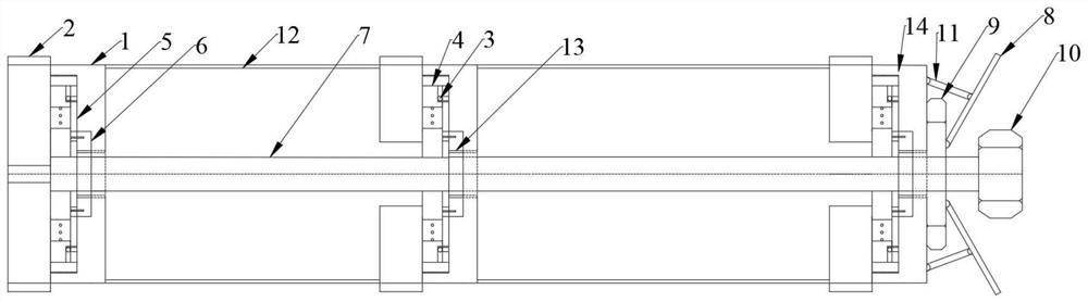
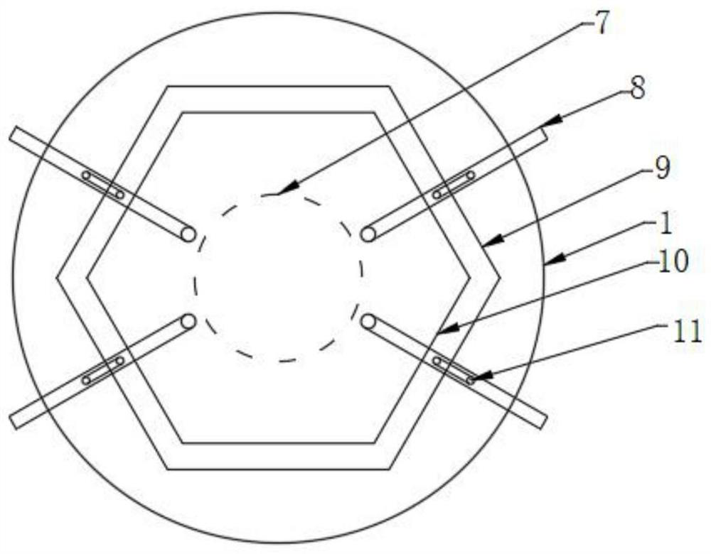
[0037] Example 1: Such as figure 1 As shown, an expansion type makes a barrier, including an outer anchor cylinder 1, an expansion, a pivot 7, a strut 8, anchor cap 10, and a bearing 12,

[0038] The outer anchor cylinder body 1 is provided with a pivot 7 in the axial center and the pivot 7 passes through the closed end of the outer anchor cylinder 1, and the anchor cap 10 is fixedly disposed on the end of the pivot 7 and anchor. The cap 10 is close to the closed end of the anchor cylinder 1, and the strut 8 is inclined to the closed end of the anchor barrel 1;

[0039] The expansion makes the pressing device comprises an inner anchor extension 2, a slider 4, a chute, and a transmission member;

[0040]The inner ring of the bearing 12 is fixed to the pivot 7, and the outer wall of the outer ring of the bearing 12 is in contact with the inner wall of the outer anchor cylinder body 1, and the outer anchor cylinder 1 is opened in the circumferential direction, the inner anchor expand...

Embodiment 2

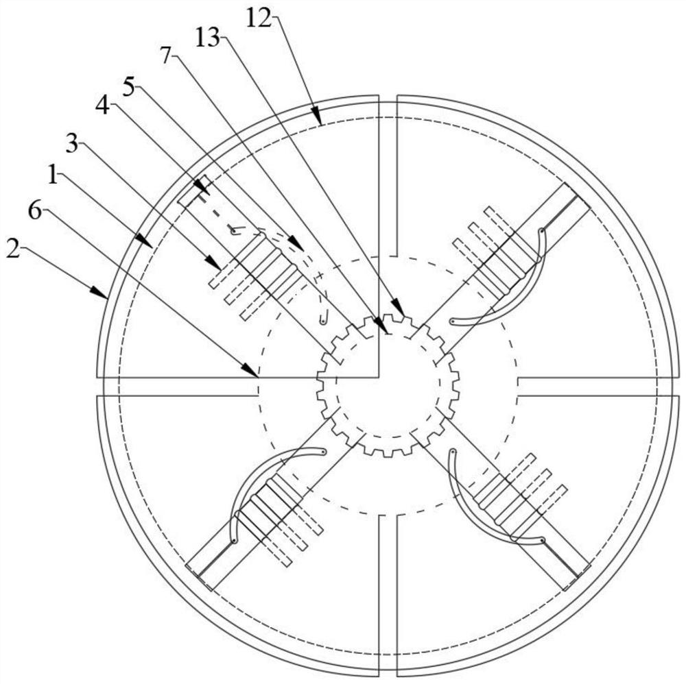
[0042] Example 2: The expansion type of the present embodiment is substantially the same as the expansion type of Example 1, and the difference is that figure 2 As shown, the sidewall of the chute has a bolt hole, and the bolt hole is fixedly provided which is stretchable shear bolt III, and the shear bolt III is perpendicular to the sliding direction of the slider 4;

[0043] The transmission member includes a transmission shaft 5, a rotary disk 6, and a gear 13, and the gear 13 is fixedly disposed on the pivot 7, the inner ring of the rotary disk 6 is engaged with the gear 13, and the rotary disk 6 is fixedly provided with a pin shaft I, the drive shaft 5 One end is arranged on the pin shaft I and the drive shaft 5 can rotate about the pin shaft 1, and the slider 4 is fixed to the pin shaft II, and the other end of the drive shaft 5 is arranged on the pin shaft II and the pin II can be wound. Pin II rotates;

[0044] The rotating disk 6 is provided with a space area having a siz...


PUM


Abstract

The invention relates to an expansion type yielding anchor rod, and belongs to the technical field of anchor rods. The expansion type yielding anchor rod comprises an outer anchor rod barrel, an inner anchor rod expansion body, a sliding block, a sliding groove, a transmission component, a pivot, a supporting rod, an anchor rod cap and a bearing, the pivot is arranged in the outer anchor rod barrel along the axial center and penetrates through the closed end of the outer anchor rod barrel, the anchor rod cap is fixedly arranged at the end of the pivot and is close to the closed end of the outer anchor rod barrel, and the supporting rod is obliquely arranged at the closed end of the outer anchor rod barrel; and an inner ring of the bearing is fixed to the pivot, the outer wall of an outer ring of the bearing makes contact with the inner wall of the outer anchor rod barrel, a through hole is formed in the outer anchor rod barrel in the axial direction, the inner anchor rod expansion body penetrates through the through hole, the sliding block is fixedly arranged on the inner side of the inner anchor rod expansion body, a disc is arranged on the pivot through a ball bearing, the sliding groove is formed in the disc in the radial direction, the sliding block is arranged in the sliding groove in a sliding mode and connected with the pivot through the transmission component. Timely supporting is combined, and the extension capacity of the anchor rod system is improved.

Description

Technical field [0001] The present invention relates to an expansion type, which belongs to the field of anchor technology. Background technique [0002] During the process of mining, slope engineering and other underground excavation, it is necessary to reinforce the broken rock, loose rock mass, etc. to prevent collapse collapse, and the anchor is the most commonly used support method in surrounding rock support. As the tension member in-depth formation, the self-organism and self-supporting ability of the geotechnical medium around the anchor can be sufficiently exported, and the extension of the deformation of the harmful deformation is controlled by means of the structural object, ensuring the stability of the structural or opening surface. sex. [0003] The grouting anchor is first drilled on the surrounding rock body, then injects the resin insertion into the drill hole, then insert the anchor into the drill hole, reaches the purpose of the anchor and the surrounding rock ...

Claims


Application Information

Patent Timeline
IPC IPC(8): E02D5/74E02D17/20
CPCE02D5/74E02D17/20E02D2600/30Y02A10/23
Inventor 侯克鹏史磊孙华芬
Owner KUNMING UNIV OF SCI & TECH
Why Eureka
Try Eureka