Non-pneumatic tire

a non-pneumatic, tire technology, applied in the field of tires, can solve the problems of poor durability of conventional non-pneumatic tires, insufficient safety, and rapid age and breakage of tires, and achieve the effect of enhancing durability

Active Publication Date: 2021-05-06
KENDA RUBBER INDUSTRIAL COMPANY
View PDF4 Cites 0 Cited by
  • Summary
  • Abstract
  • Description
  • Claims
  • Application Information

AI Technical Summary

Benefits of technology

The present invention is a non-pneumatic tire that includes a spoke layer with bending spokes. This design prevents friction and damage between the spokes when the tire is squeezed under a heavy weight. The bending spokes also help the tire bend in the same direction when compressed, reducing the likelihood of contact between adjacent spokes and improving durability and rigidity of the tire.

Problems solved by technology

However, when the pneumatic tires are excessively worn or punctured by sharp objects, the pneumatic tires pop and deflate, so that the vehicle is unable to run, even causing the vehicle to lose control and overturn, resulting in injuries and deaths to drivers and passengers.
For example, when the conventional non-pneumatic tire 1 is disposed on a vehicle and is driven to rotate at high speed, the spoke assemblies 10, which are squeezed and bent, will frequently and severely get in contact with and rub against the adjacent spoke assemblies 10, and may even cause a material of the spoke assemblies 10, which are bent and squeezed, to rapidly age and break due to friction and heat generated by friction, so that the conventional non-pneumatic tire 1 has poor durability and insufficient safety.

Method used


Image

  • Non-pneumatic tire
  • Non-pneumatic tire
  • Non-pneumatic tire

Examples


Embodiment Construction

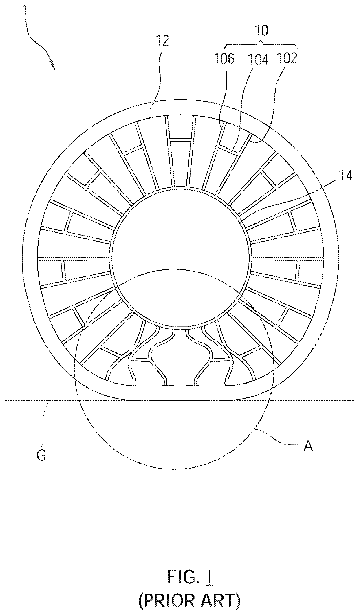
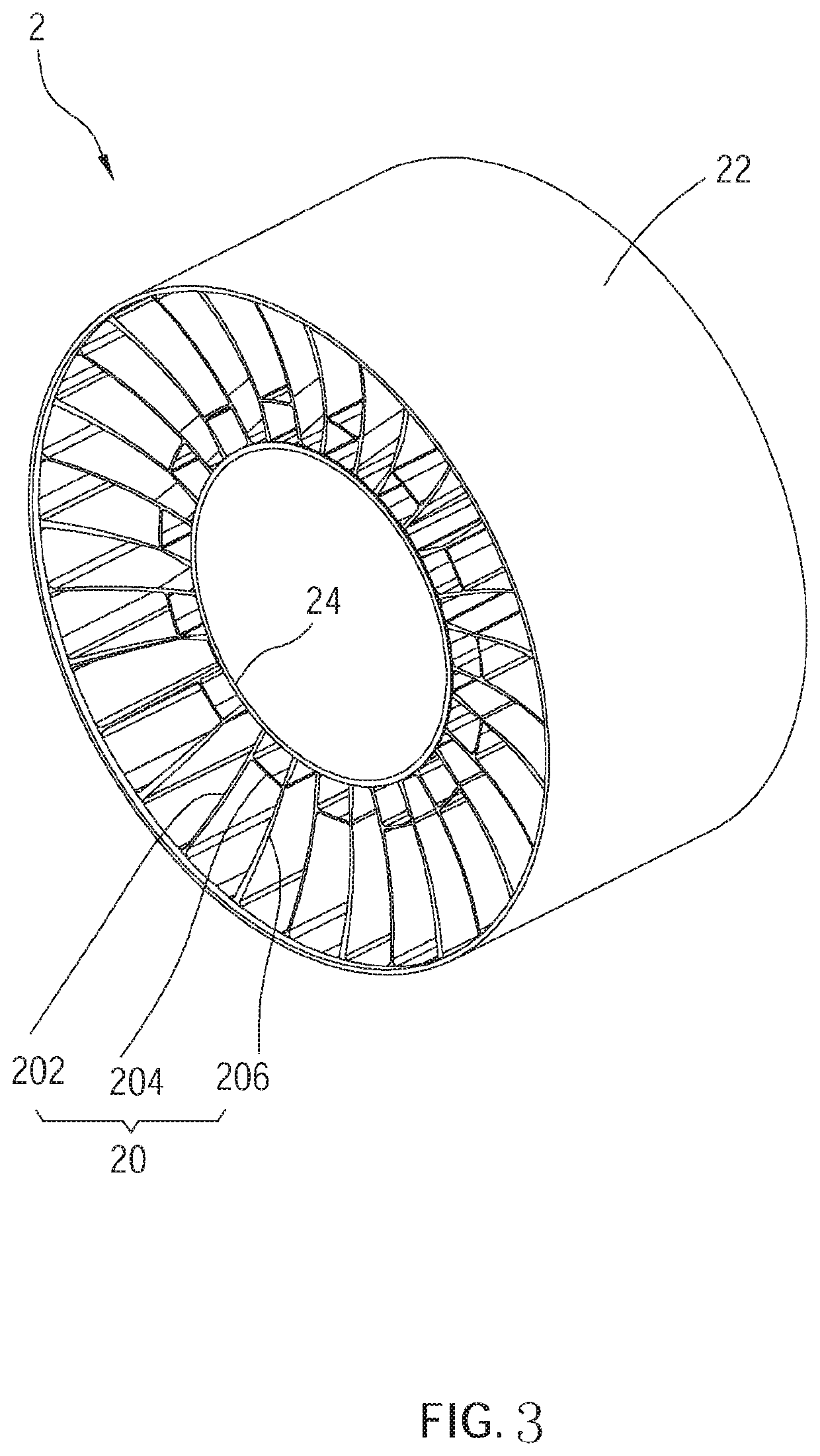
[0016]A non-pneumatic tire 2 according to an embodiment of the present invention is illustrated in FIG. 3 to FIG. 6 and is adapted to be disposed on a drive shaft or a wheel rim of matching size depending on the requirements, wherein FIG. 3 is a perspective view of the non-pneumatic tire 2 according to the embodiment of the present invention; FIG. 4 is a side view of the non-pneumatic tire 2 shown in FIG. 3; FIG. 5 is another side view of the non-pneumatic tire 2 shown in FIG. 3 showing a bottom of the non-pneumatic tire 2 is squeezed under a weight; FIG. 6 is an enlarged partial view of a marked region B in FIG. 5.

[0017]The non-pneumatic tire 2 includes a tread layer 22 and a spoke layer, wherein the tread layer 22 is annular and is adapted to get in contact with a ground G. In the current embodiment, the tread layer 22 is an outermost layer of the non-pneumatic tire 2, so that the tread layer 22 has a maximum outer diameter of the non-pneumatic tire 2.

[0018]The spoke layer include...


PUM


Abstract

A non-pneumatic tire includes a tread layer and a spoke layer including an inner cylinder and several spoke assemblies. The tread layer is annular and has a maximum outer diameter of the non-pneumatic tire and is adapted to be in contact with a ground. The spoke assemblies extend in a radial direction of the non-pneumatic tire and are arranged around an axial core of the non-pneumatic tire. An end of each spoke assembly is connected to the inner cylinder, and another end thereof is connected to the tread layer. Each spoke assembly includes a straight spoke, a bending spoke, and a connecting rib. Each bending spoke includes a first segment and a second segment, which are not connected in a straight line. Each connecting rib has a first end connected to the straight spoke and a second end opposite to the first end and connected to the bending spoke. When the non-pneumatic tire bears a weight and is squeezed, the spoke assemblies do not get in contact with one another.

Description

BACKGROUND OF THE INVENTIONTechnical Field[0001]The present invention relates generally to a tire, and more particularly to a non-pneumatic tire.Description of Related Art[0002]For a long time, ordinary vehicles (e.g. automobiles, motorcycles, bicycles) used to use pneumatic tires as the main components of vehicle movement. However, when the pneumatic tires are excessively worn or punctured by sharp objects, the pneumatic tires pop and deflate, so that the vehicle is unable to run, even causing the vehicle to lose control and overturn, resulting in injuries and deaths to drivers and passengers.[0003]Therefore, a non-pneumatic tire has been developed to replace traditional pneumatic tires, thereby completely overcoming the problem of a flat tire and air leakage of traditional tires. A conventional non-pneumatic tire 1 is illustrated in FIG. 1 and includes a tread layer 12 and a spoke layer, wherein the tread layer 12 is adapted to get in contact with a ground G. The spoke layer inclu...

Claims


Application Information

Patent Timeline
Patent Type & Authority Applications(United States)
IPC IPC(8): B60C7/14B60C7/10
CPCB60C7/14B60C2007/146B60C7/102B60C7/146
Inventor YANG, CHI-JENHUANG, MIN-FANJIANG, JIA-YI
Owner KENDA RUBBER INDUSTRIAL COMPANY
Why Eureka
Try Eureka