An automatic battery replacement device for a new energy vehicle

A new energy vehicle, automatic technology, applied in the direction of electric vehicles, charging stations, vehicle parts, etc., can solve the problem of reducing the speed of battery replacement, and achieve the effect of increasing the speed and improving the replacement efficiency.

Active Publication Date: 2022-03-15
东营科技职业学院
View PDF5 Cites 0 Cited by
  • Summary
  • Abstract
  • Description
  • Claims
  • Application Information

AI Technical Summary

Problems solved by technology

[0003] The existing new energy vehicles are powered partly or entirely from the battery, and the service life of the battery will gradually shorten with the increase of the service life. When the capacity of the battery is lower than a certain value, the battery needs to be replaced. Generally, it is necessary to drive the car to the designated place first, and then lift it up with the help of lifting equipment. When the battery compartment at the bottom is exposed, move the battery replacement device along the track to the bottom of the battery compartment and adjust it to a suitable height. The battery can be held by the battery changer, and then the screws holding the battery are removed manually, at which point the old battery falls on top of the battery changer, and the battery changer is then lowered so that the old battery is on top of the battery changer. Under the support of the battery, it is taken out from the battery compartment and moved along the track. When the new battery is placed on the top of the battery replacement device, the battery replacement device needs to return to the original position with the new battery. However, due to the existing battery The replacement unit is not positioned where it sits on the track when the old battery is removed, so when the battery changer transports the new battery along the track to the bottom of the battery compartment, it takes time for the new battery to fit into the car's battery compartment alignment, which reduces the speed of battery replacement

Method used


Image

  • An automatic battery replacement device for a new energy vehicle
  • An automatic battery replacement device for a new energy vehicle
  • An automatic battery replacement device for a new energy vehicle

Examples


Embodiment Construction

[0028] In order to make the purpose, technical solutions and advantages of the embodiments of the present invention more clear, the technical solutions in the embodiments of the present invention will be clearly and completely described below in conjunction with the accompanying drawings in the embodiments of the present invention. Obviously, the described embodiments It is a part of embodiments of the present invention, but not all embodiments. Based on the embodiments of the present invention, all other embodiments obtained by persons of ordinary skill in the art without making creative efforts belong to the protection scope of the present invention.

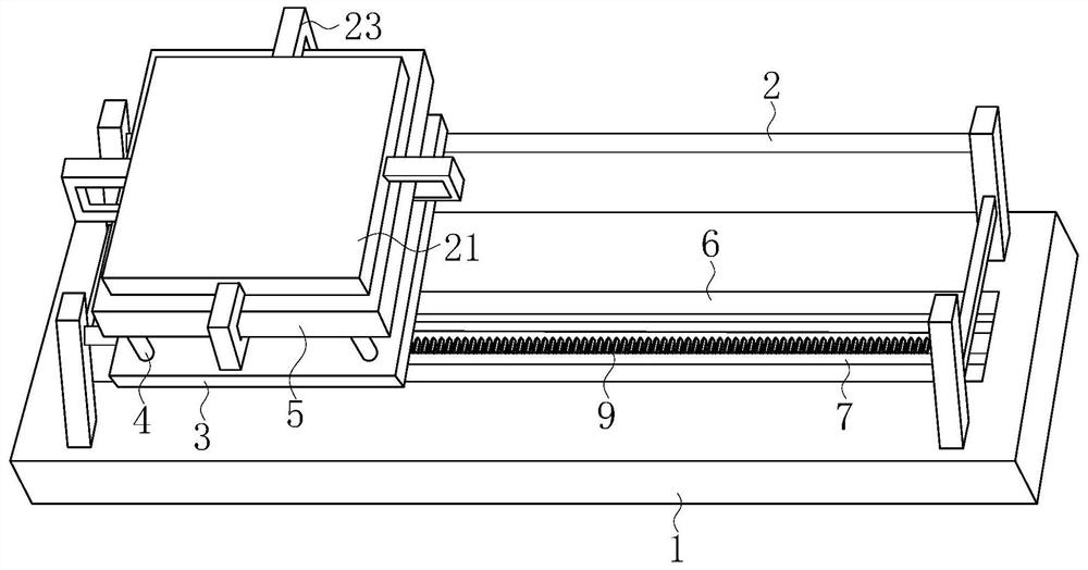
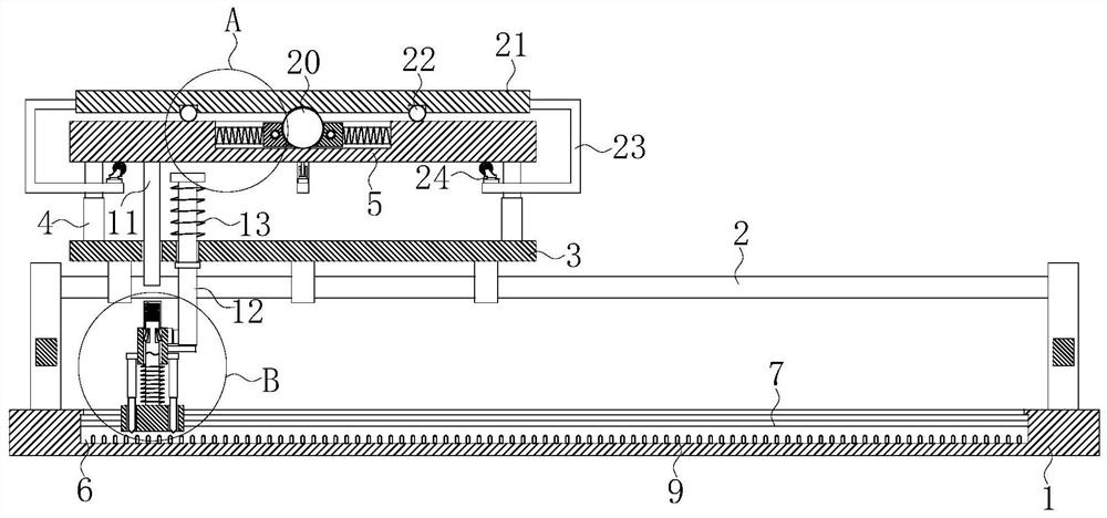
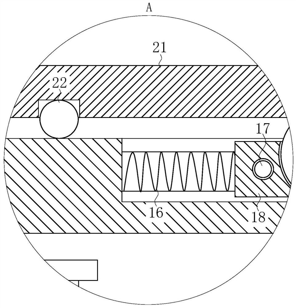
[0029] The present invention provides such Figure 1-6 The shown automatic battery replacement device for a new energy vehicle includes a base 1, and the four corners of the base 1 are fixedly connected with supporting columns, between the two supporting columns on the front side and on the rear side. The first sliding rod 2 ...


PUM


Abstract

The invention discloses an automatic battery replacement device for a new energy vehicle, which belongs to the technical field of vehicle battery replacement, and includes a base. The positions near the four corners of the base are fixedly connected with support columns, and the two support columns on the front side The first slide bar is fixedly connected between the two pillars on the rear side, and the tops of the two first slide bars are slidably connected to the same slide plate, and the top of the slide plate is close to the four corners. It is fixedly connected with a hydraulic rod. The present invention is equipped with a telescopic rod. After the old battery is removed, the support plate moves downward. When popping out of the storage slot, the casing is locked at the current position, and the telescopic rod is clamped with the limit block. At this time, the column and the first slider are locked at the current position, thereby positioning the battery compartment. function, thereby improving the battery replacement efficiency.

Description

technical field [0001] The invention belongs to the technical field of vehicle battery replacement, in particular to an automatic battery replacement device for new energy vehicles. Background technique [0002] New energy vehicles refer to vehicles with advanced technical principles, new technologies and new structures that use unconventional vehicle fuels as power sources (or use conventional vehicle fuels and adopt new vehicle power devices); new energy vehicles mainly Divided into four categories: hybrid electric vehicles (HEV), pure electric vehicles (BEV, including solar vehicles), fuel cell electric vehicles (FCEV), other new energy (such as super capacitors, flywheels and other high-efficiency energy storage) vehicles Wait. [0003] The existing new energy vehicles are powered partly or entirely from the battery, and the service life of the battery will gradually shorten with the increase of the service life. When the capacity of the battery is lower than a certain ...

Claims


Application Information

Patent Timeline
Patent Type & Authority Patents(China)
IPC IPC(8): B60L53/80
CPCB60L53/80Y02T10/70Y02T10/7072
Inventor 陈为全赵美华
Owner 东营科技职业学院
Why Eureka
Try Eureka