
a valve bridge

A valve, transition fit technology, applied in valve devices, machines/engines, mechanical equipment, etc., can solve the problems of short life, poor shock absorption and noise reduction, and achieve the effect of improving life, avoiding noise, and reducing impact force.

Active Publication Date: 2022-06-24
HENAN DIESEL ENGINE IND
View PDF6 Cites 0 Cited by
  • Summary
  • Abstract
  • Description
  • Claims
  • Application Information

AI Technical Summary

Problems solved by technology

[0004] The purpose of the present invention is to provide a valve bridge, which solves the technical problems of poor shock absorption and noise reduction performance and short service life of the valve bridge in the prior art

Method used


Image

  • a valve bridge
  • a valve bridge
  • a valve bridge

Examples


Embodiment Construction

[0033] In order to make the objectives, technical solutions and advantages of the present invention clearer, the technical solutions of the present invention will be described in detail below. Obviously, the described embodiments are only some, but not all, embodiments of the present invention. Based on the embodiments of the present invention, all other implementations obtained by those of ordinary skill in the art without creative work fall within the protection scope of the present invention.

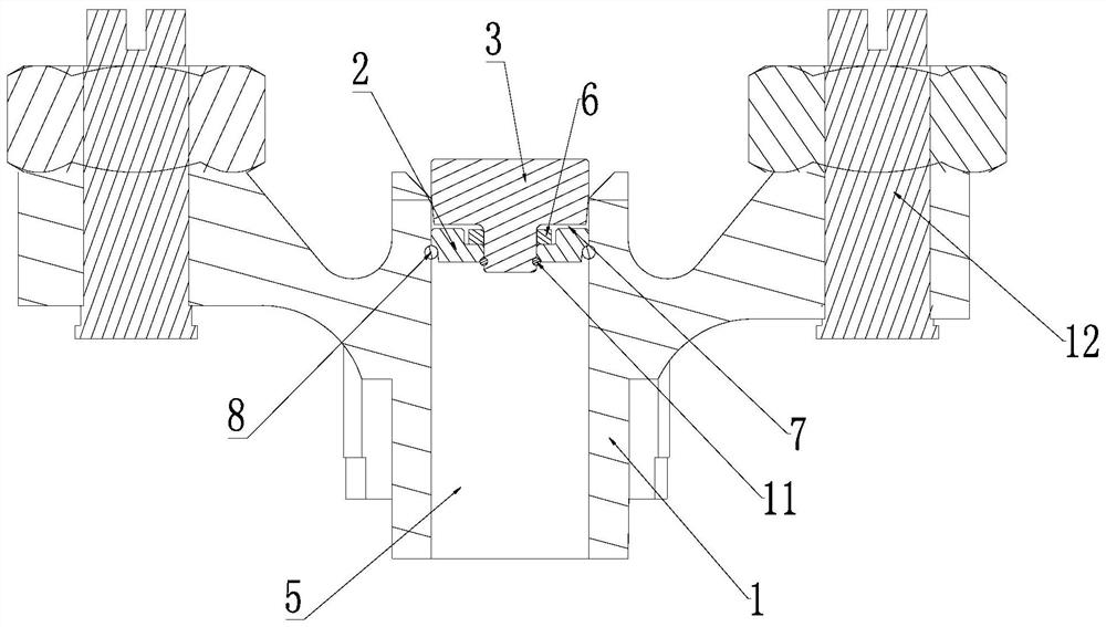
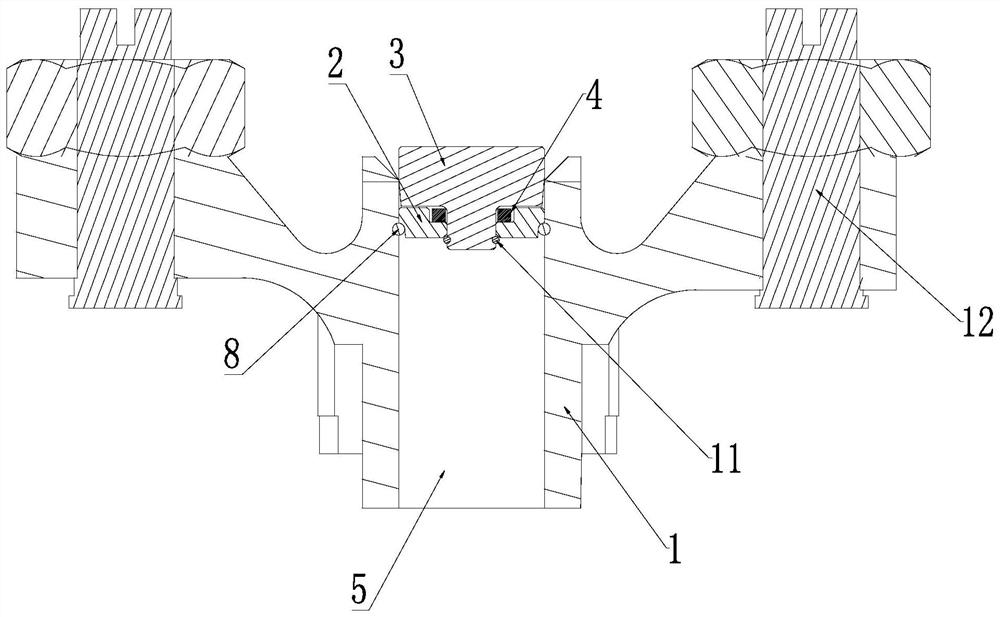
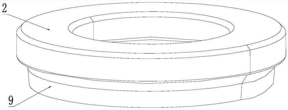
[0034] A specific embodiment of the present invention provides a valve bridge, combined with an attached figure 1 - Attached Figure 5 , including the bridge body 1, the bearing body 2, the cushion block 3 and the damping part 4, the bridge body 1 is the main structure of the valve bridge, the bearing body 2, the cushion block 3 and the shock absorption part 4 are all arranged on the bridge body 1, a through hole 5 is set on the bridge body 1; the bearing body 2 and the cushion blo...


PUM


Abstract

The invention provides a valve bridge, which relates to the technical field of engine accessories, and solves the technical problems of poor damping and noise reduction performance and short service life of the valve bridge in the prior art. The valve bridge includes a bridge body, a carrier, a pad and a shock absorber, wherein a through hole is arranged on the bridge body; the carrier is arranged in the through hole, and the pad and the bearing The body is connected; the cushion block is arranged in the through hole, and the transition fit between the cushion block and the bridge body; the shock absorbing part is arranged between the bearing body and the cushion block. The present invention is used at the engine valve, adopts the movable connection and the damping structure of the shock-absorbing part, plays the role of shock-absorbing and noise-reducing. It acts on one point, significantly improving the life of the block.

Description

technical field [0001] The invention relates to the technical field of engine accessories, in particular to a valve bridge. Background technique [0002] With the rapid development of diesel engines and the increasing pursuit of noise reduction, the original models are limited in terms of space and rigidity, and it is impossible to arrange hydraulic tappets or hydraulic rocker arms related oil passages and components. The traditional design will impact the rocker arm. The load acts on the center of the bridge, so that the rocker arm always acts on the center of the bridge, which causes the impact force to act at one point, and it is easy to cause fatigue damage when used for a long time. [0003] Therefore, it is necessary to design a valve bridge to solve the problems of poor damping and noise reduction performance and short service life of the current valve bridge. SUMMARY OF THE INVENTION [0004] The purpose of the present invention is to provide a valve crossing brid...

Claims


Application Information

Patent Timeline
Patent Type & Authority Patents(China)
IPC IPC(8): F01L1/20F01L1/46
CPCF01L1/205F01L1/46
Inventor 牛晓晓宋杨王志磊
Owner HENAN DIESEL ENGINE IND
Learn More