
Recovery treatment device applied to concentrated water of chemical water production system

A technology for recovery and treatment of concentrated water, applied in water/sewage treatment, multi-stage water/sewage treatment, neutralized water/sewage treatment, etc., can solve waste of water resources, impurities prone to salt, and uneven filtration of solid substances And other issues

Pending Publication Date: 2021-08-10
巴基斯坦卡西姆港发电有限公司
View PDF6 Cites 0 Cited by
  • Summary
  • Abstract
  • Description
  • Claims
  • Application Information

AI Technical Summary

Problems solved by technology

For the purpose of anti-scaling of conventional reverse osmosis equipment, its water recovery rate generally does not exceed 75%, which is equivalent to 25% of concentrated water that needs to be recycled or discharged. Scaling substances have a tendency to scale. In the reverse osmosis system that uses reclaimed water as the water source, there are still organic indicators COD (Chemical Oxygen Demand, chemical oxygen demand) that exceed the discharge standard. Therefore, whether the reverse osmosis concentrated water is discharged up to the standard or recycled The treatment is difficult to a certain extent. Some enterprises consider that the concentrated water is difficult to recycle and the investment is large, so they directly discharge it, wasting water resources in vain. In today's relative shortage of water resources, this 25% concentrated water is very recyclable. Value, the existing filtration is through centrifugal shunt filtration, which is prone to uneven filtration of solid matter, which makes the extraction of salt prone to impurities in the later stage. In view of this, in-depth research on the above problems has resulted in this case.

Method used


Image

  • Recovery treatment device applied to concentrated water of chemical water production system
  • Recovery treatment device applied to concentrated water of chemical water production system
  • Recovery treatment device applied to concentrated water of chemical water production system

Examples


Embodiment Construction

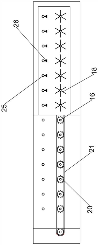
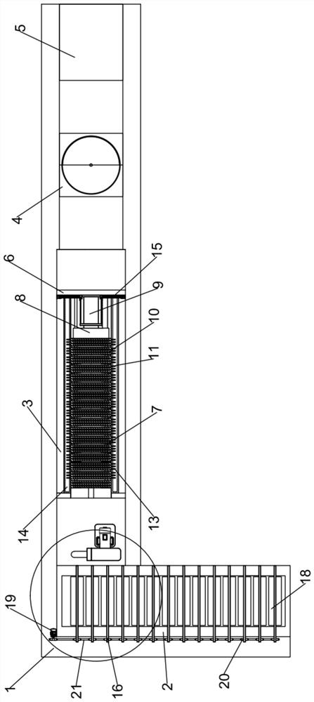
[0027] The present invention is specifically described below in conjunction with accompanying drawing, as Figure 1-5As shown, a recovery and treatment device applied to concentrated water in a chemical water system includes: a recovery support 1, a mixing tank 2, a filter table 3, an evaporation tank 4 and a cooling tank 5, and the recovery support 1 is installed on the On the mixing and stirring box 2, the filtering platform 3, the evaporation box 4 and the cooling box 5, a mixing and stirring structure is installed in the mixing and stirring box 2, a shunt structure is installed in the described filtering platform 3, and a Evaporation structure, cooling structure is installed in the cooling box 5; the split flow structure includes: extrusion bracket 6, two pairs of support limit shafts 7 with the same structure, extrusion plate 8, extrusion hydraulic cylinder 9, several Extruded concave plates 10 with the same structure, several filter plates 11 with the same structure, sev...


PUM


Abstract

The invention discloses a recovery treatment device applied to concentrated water of a chemical water production system. The recovery treatment device comprises a recovery support, a mixing and stirring box, a filter table, an evaporation box and a cooling box, the recovery support is mounted on the mixing and stirring box, the filter table, the evaporation box and the cooling box, a mixing and stirring structure is mounted in the mixing and stirring box, a flow dividing structure is mounted in the filtering table, a steaming structure is mounted in the evaporation box, and a cooling structure is mounted in the cooling box. The invention relates to the technical field of concentrated water filtration, neutralization liquid and concentrated water are mixed and stirred through the mixing and stirring structure, reacted liquid is subjected to high-pressure extrusion filtration through the flow dividing structure, meanwhile, water in mixed liquid is filtered through cooperation of a plurality of filter plates and high pressure, and through high-pressure extrusion filtration, the phenomenon of blockage still occurs during centrifugal filtration, and meanwhile, salt evaporation is carried out on the filtered liquid through the evaporation structure.

Description

technical field [0001] The invention relates to the technical field of concentrated water filtration, in particular to a recovery and treatment device for concentrated water in a chemical water production system. Background technique [0002] At present, reverse osmosis has been widely used as a pre-desalination device in the field of water treatment. For the purpose of anti-scaling in conventional reverse osmosis equipment, its water recovery rate generally does not exceed 75%, which is equivalent to 25% of concentrated water that needs to be recycled or discharged. Since the concentrated water is concentrated 4 times through reverse osmosis, its calcium, magnesium, silicon Scaling substances have a tendency to scale. In the reverse osmosis system that uses reclaimed water as the water source, there are still organic indicators COD (Chemical Oxygen Demand, chemical oxygen demand) that exceed the discharge standard. Therefore, whether the concentrated reverse osmosis water i...

Claims


Application Information

Patent Timeline
IPC IPC(8): C02F9/10
CPCC02F9/00C02F1/66C02F1/001C02F1/04C02F1/043
Inventor 吴宇奚鹏李玉军赵作起杨庚银
Owner 巴基斯坦卡西姆港发电有限公司
Learn More