circular symmetry 0n mode filter

A circularly symmetric, filter technology, applied in waveguide-type devices, circuits, electrical components, etc., can solve the problems of reduced radial branch amplitude and phase consistency, limited operating bandwidth and efficiency, and reduced power combining efficiency, etc. Improved pattern purity, high power capacity, and compact structure

Active Publication Date: 2022-03-29
UNIV OF ELECTRONICS SCI & TECH OF CHINA
View PDF0 Cites 0 Cited by
  • Summary
  • Abstract
  • Description
  • Claims
  • Application Information

AI Technical Summary

Problems solved by technology

[0004] In fact, based on circular symmetry TE 0n In the waveguide space radial power combination technology of the mode, due to the circular symmetry TE used in the power combination 0n The mode is a high-order mode, which is easily affected by the low-order mode; and the non-ideality of any link in the synthesis system may lead to non-circular symmetric TE 0n pattern generation
These non-circular symmetric modes severely limit the circular symmetry-based TE 0n The working bandwidth and efficiency of waveguide space radial power combining technology in corresponding power combining system
[0005] In addition, based on circular symmetry TE 0n In the actual system application of the waveguide space radial power combination of the mode, it is often necessary to realize the common mode of the system (mostly the rectangular waveguide TE10 mode, the microstrip TEM mode or the coaxial TEM mode) and the circular symmetric TE mode. 0n The transition conversion of the mode signal, so that the mode converter introduced in practical applications will definitely stimulate other non-circularly symmetrical TEs due to structural or process factors. 0n mode, thus destroying the amplitude and phase consistency of each radial branch in the system and reducing the power combination efficiency

Method used


Image

  • circular symmetry  <sub>0n</sub> mode filter
  • circular symmetry  <sub>0n</sub> mode filter
  • circular symmetry  <sub>0n</sub> mode filter

Examples


Embodiment 1

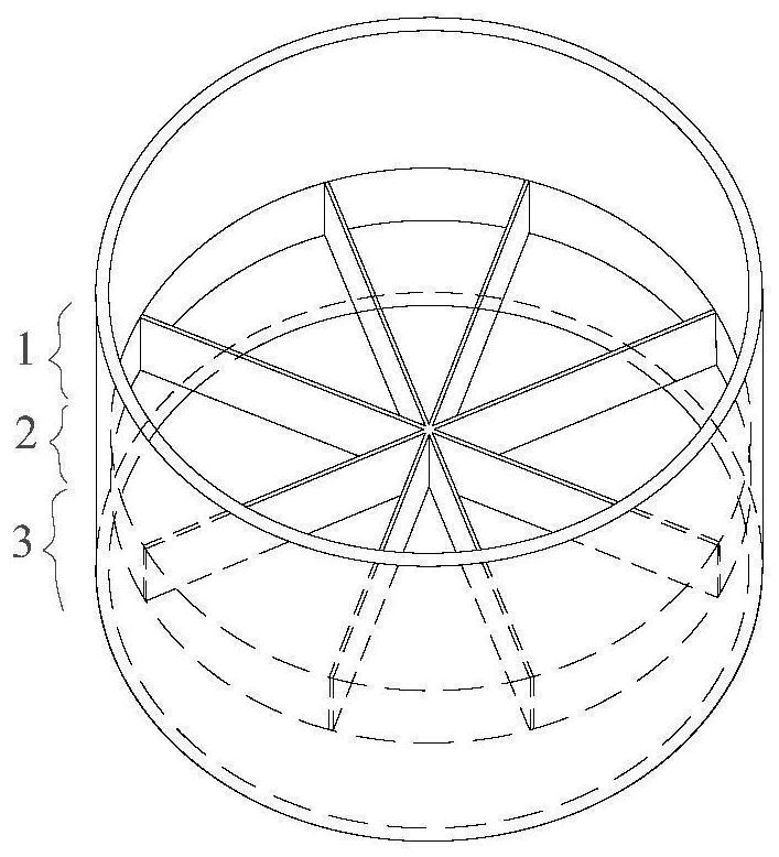
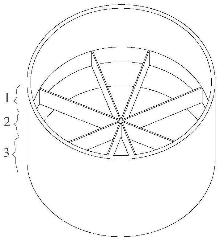
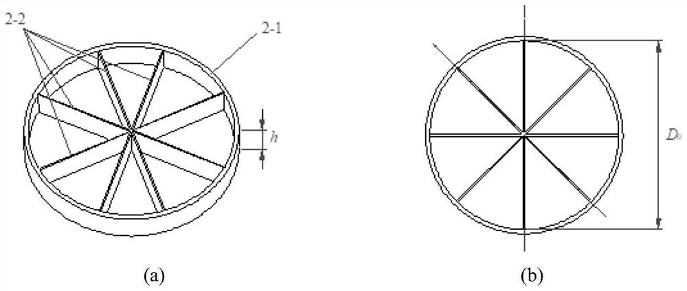
[0030] As shown in Figure 1, a circular symmetric TE 0n The mode filter includes the first circular waveguide section 1, the mode filtering section 2 and the second circular waveguide section 3 connected concentrically from top to bottom, all of which are hollow metal cylindrical cavities, and the outer surfaces of the three form the same cylinder Surface; the first circular waveguide section 1 and the second circular waveguide section 3 have the same size and the inner diameter is D, and the inner diameter of the mode filter section 2 is D 0 , the first circular waveguide section 1 is used as the input interface of the mode filter; the second circular waveguide section 3 is used as the output circular waveguide interface of the mode filter; the mode filter section 2 is embedded with a plurality of radial arrangements with the same shape and size A rectangular metal diaphragm 2-2, a plurality of metal diaphragms 2-2 are evenly distributed in the radial direction on a circle wi...

Embodiment 2

[0042] The difference between this embodiment and embodiment 1 is: D 0 =D.

Embodiment 3

[0044] The difference between this embodiment and embodiment 1 is: D 0


PUM


Abstract

The invention provides a circular symmetric TE 0n The mode filter includes the first circular waveguide section, the mode filtering section and the second circular waveguide section concentrically connected in sequence from top to bottom, all of which are hollow metal cylindrical cavities, and the first circular waveguide section serves as the core of the mode filter The input interface; the second circular waveguide section is used as the output circular waveguide interface of the mode filter; the mode filter section is embedded with a plurality of radially arranged rectangular metal diaphragms with the same shape and size, and the plurality of metal diaphragms are in the form of the mode filter section. The center is the center of the circle, and the length of the metal diaphragm is radially evenly distributed on the circumference; the circle is symmetrical TE 0n The mode filter has a compact structure, is easy to process and realize, and has high power capacity, and can be used for TE based on circular waveguide 0n mode power combining system, improving circular waveguide-based TE 0n The effective operating frequency bandwidth and combining efficiency of the mode radial power combiner realize microwave and millimeter wave multi-channel broadband high-efficiency and high-power combining.

Description

technical field [0001] The invention belongs to the technical field of microwave and millimeter wave terahertz, in particular to the technical field of millimeter wave terahertz waveguide space radial power combination. Background technique [0002] In the field of microwave and millimeter wave multi-channel high power combination, based on circular symmetric TE 0n Mode-based waveguide space radial power combining technology has attracted much attention due to its technical characteristics of multiple combining branches, low loss and large power capacity. In this type of combination technology, multiple single-mode (rectangular waveguide TE10 mode or microstrip line TEM mode) branch power signals are combined into a circularly symmetrical TE in the form of a radial frame. 0n Mode signal, so as to realize the waveguide space multi-path direction power combination. [0003] Like other power amplification and combination technologies, the radial power combination process of t...

Claims


Application Information

Patent Timeline
Patent Type & Authority Patents(China)
IPC IPC(8): H01P1/20H01P1/213
CPCH01P1/20H01P1/213
Inventor 谢小强李雪鹏张译戈闫卓伟马柱荣原铭伟龚志伟
Owner UNIV OF ELECTRONICS SCI & TECH OF CHINA
Why Eureka
Try Eureka