Vehicle collision emergency alarm calling device

An emergency alarm and call device technology, applied in the field of intelligent traffic management, can solve the problems of people's life and property loss, high setting height, dim light, etc., to reduce the loss of life and property, speed up the response speed, and prevent secondary accidents.

Pending Publication Date: 2021-08-06
郑卫华
View PDF4 Cites 0 Cited by
  • Summary
  • Abstract
  • Description
  • Claims
  • Application Information

AI Technical Summary

Problems solved by technology

[0003] In the prior art, variable information boards are installed outside the tunnel and above the tunnel. The real area of ​​these variable information boards is small, and the installation height is high, which is not easy to attract the driver's attention, especially in low visibility, It is more difficult for the driver to recognize the information on the variable information board in the case of a short line of sight
In addition, the existing technology lacks a way to effectively transmit the accident signal to every driver entering the tunnel in a timely manner. The traditional method is generally that after a vehicle accident or breakdown occurs in the tunnel, the vehicle in the accident turns on the fault light, dials for help, waits The traffic police deal with it, but because the light in the tunnel is relatively dim, in the process of waiting for the traffic police, when the subsequent vehicles enter the tunnel, especially when the vehicles driving on the expressway enter the tunnel, the fault light signal of the faulty vehicle is often not seen in time. Make the driver unable to do a good job of deceleration and avoidance in time, resulting in secondary accidents and serious losses to people's lives and property

Method used


Image

  • Vehicle collision emergency alarm calling device
  • Vehicle collision emergency alarm calling device
  • Vehicle collision emergency alarm calling device

Examples


Embodiment Construction

[0028] The following will clearly and completely describe the technical solutions in the embodiments of the present invention with reference to the drawings in the embodiments of the present invention.

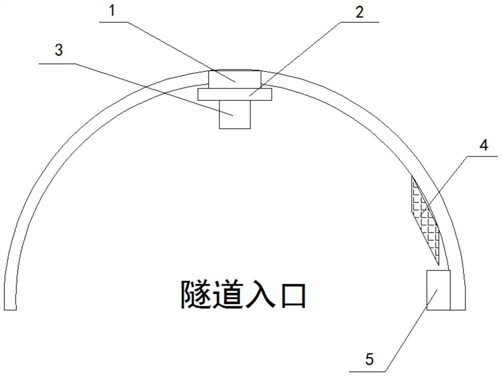
[0029] Such as Figure 1-6 As shown, one embodiment of the present invention discloses a vehicle collision emergency alarm calling device, including an accident alarm system, the accident alarm system includes an alarm base station, a signal repeater, an on-site alarm system, a remote controller and a monitoring center, and the alarm base station Distributed inside the tunnel to start the alarm signal when an accident occurs in the tunnel. The alarm base station includes a circuit part and an electromechanical drive part. The circuit part includes a Zigbee communication module and a main control circuit module. The alarm signal of the alarm base station passes through the wireless network in the Each alarm base station in the tunnel is transmitted, and the accident alarm signa...


PUM


Abstract

The invention discloses a vehicle collision emergency alarm calling device, and relates to the technical field of intelligent traffic management. The device comprises an accident alarm system, the accident alarm system comprises an alarm base station, a signal repeater, a field alarm system, a remote controller and a monitoring center. The field alarm system comprises a plasma laser transmitter, a laser diffusion device, a projector, a control box and a fog screen machine, the plasma laser transmitter and the projector are installed at the arch crown of a tunnel portal, the laser diffusion device is installed at the head of the laser transmitter, the control box and the projector are electrically connected with the monitoring center, and the fog screen machine is laid along the secondary linings of the tunnel portal. Based on a Zigbee wireless communication networking technology, a series of wireless alarm base stations and a field alarm system outside the tunnel are arranged in the tunnel, a laser virtual wall is formed at the tunnel portal by adopting a laser technology, traffic accident image information in the tunnel is displayed on the virtual wall, vehicles outside the tunnel are warned not to enter the tunnel any more, and secondary accidents are prevented.

Description

technical field [0001] The invention relates to the technical field of intelligent traffic management, in particular to a vehicle collision emergency alarm calling device. Background technique [0002] The emergence of tunnels has greatly reduced the operating mileage between two points, and has also improved the operational efficiency of highways. The tunnel is a relatively closed site, and it is also a place where traffic safety accidents frequently occur. Once a traffic accident occurs, it is difficult for drivers outside the tunnel to know. Often, vehicles outside the tunnel still risk their lives without knowing that a traffic accident occurred inside the tunnel. However, the high-speed driving into the tunnel caused rear-end collisions and collisions, which caused secondary accidents. Especially for highway tunnels, once a high-speed vehicle enters a tunnel where a traffic safety accident occurs, it is difficult to brake quickly, and chain collisions are likely to occ...

Claims


Application Information

Patent Timeline
IPC IPC(8): G08G1/16H04W4/80G08B25/00B05B9/00
CPCG08G1/165H04W4/80G08B25/009B05B9/00
Inventor 郑卫华祝振敏刘文轩周胜涛詹昊德刘为焜
Owner 郑卫华
Why Eureka
Try Eureka