


Quick Research
Generate reliable direction feasibility study reports for your R&D in just a few steps.

Technical Q&A
Discover and master advanced knowledge NOW. Basics, ideas, possibilities, all at once.

Find Solutions
As an expert in R&D theories, this can generate solutions to your technical problems instantly.

Evaluate Feasibility
Analyze your overall solution with one click, know your potential R&D risks in advance.

Monitor Landscape
Get weekly tech updates, stay abreast of the latest tech innovations and key insights.
Visual inertial odometer scale estimation method and device
An odometer and inertial technology, applied in the field of autonomous driving, can solve the problems of scale divergence, positioning accuracy does not meet the requirements of mapping, and achieve the effect of accurate accuracy and cheap calculation.
- Summary
- Abstract
- Description
- Claims
- Application Information
AI Technical Summary
Problems solved by technology
Method used
Image

Examples
Embodiment 1
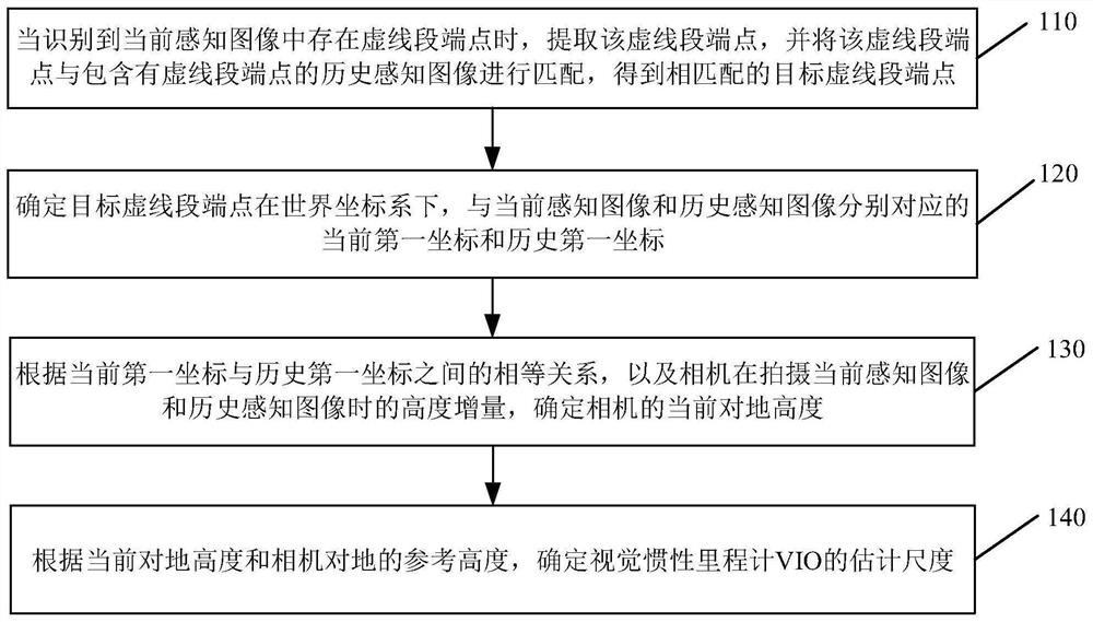
[0085] see figure 1 , figure 1 is a schematic flow chart of a visual-inertial odometry scale estimation method provided by an embodiment of the present invention. This method is typically applied to scenarios where GPS signals are interfered or affected during automatic driving, such as long tunnel scenarios. The method can be performed by a visual-inertial odometer estimating device, which can be realized by means of software and / or hardware, and generally can be integrated in a vehicle-mounted computer, a vehicle-mounted industrial personal computer (Industrial personalComputer, IPC), and other vehicle-mounted terminals. The embodiments of the invention are not limited. Such as figure 1 As shown, the method provided in this embodiment specifically includes:
[0086] 110. When it is recognized that there is an endpoint of a dashed line segment in the current perceptual image, extract the endpoint of the dashed line segment, and match the endpoint of the dashed line segmen...
Embodiment 2
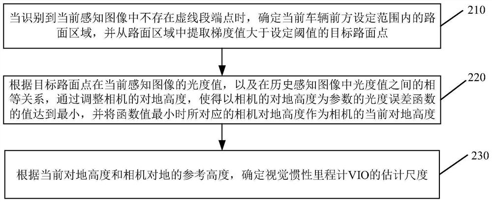
[0106] see figure 2 , figure 2 is a schematic flow chart of a visual-inertial odometry scale estimation method provided by an embodiment of the present invention. This embodiment is optimized on the basis of the foregoing embodiments, and is mainly applied to a road scene where there is no endpoint of a dashed line segment on the road. Such as figure 2 As shown, the method includes:
[0107] 210. When it is recognized that there is no endpoint of the dotted line segment in the current perception image, determine the road surface area within the set range ahead of the current vehicle, and extract the target road surface point whose gradient value is greater than the set threshold from the road surface area.
[0108] Exemplarily, when extracting target road surface points, the road surface area can be divided into grids, and feature points whose gradient values are greater than the set threshold can be extracted from each grid, so as to ensure that enough and distributed...
Embodiment 3
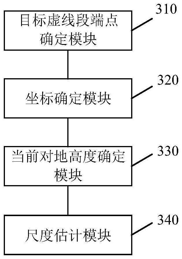
[0119] see image 3 , image 3 It is a structural block diagram of a visual-inertial odometry scale estimation device provided by an embodiment of the present invention. Such as image 3As shown, the device specifically includes: a target dashed line endpoint determination module 310, a coordinate determination module 320, a current altitude determination module 330, and a scale estimation module 340; wherein,
[0120] The target dashed line segment endpoint determining module 310 is configured to extract the dashed line segment endpoint when it is recognized that there is a dashed line segment endpoint in the current perception image, and match the dashed line segment endpoint with the historical perception image containing the dashed line segment endpoint , get the endpoint of the matching target dotted line segment;
[0121] The coordinate determination module 320 is configured to determine the current first coordinate and the historical first coordinate of the end point...
PUM
 Abstract
Description
Claims
Application Information
 - R&D Engineer
- R&D Manager
- IP Professional
- Industry Leading Data Capabilities
- Powerful AI technology
- Patent DNA Extraction
Browse by: Latest US Patents, China's latest patents, Technical Efficacy Thesaurus, Application Domain, Technology Topic, Popular Technical Reports.
© 2024 PatSnap. All rights reserved.Legal|Privacy policy|Modern Slavery Act Transparency Statement|Sitemap|About US| Contact US: help@patsnap.com