
Automatic-backwashing sedimentation type micro-filter

A technology of backwashing and microfiltration, applied in the direction of filtration separation, filtration circuit, separation method, etc., can solve problems such as sudden start of water pump, affecting the service life of motor, and water escape, so as to achieve simple replacement of drum filter and increase work Stability, the effect of increasing the durability of the device

Pending Publication Date: 2021-08-06
广西木壳科技有限公司
View PDF0 Cites 2 Cited by
  • Summary
  • Abstract
  • Description
  • Claims
  • Application Information

AI Technical Summary

Problems solved by technology

[0003] However, the existing microfilters have the following problems in use: (1) the automatic backwashing control method is unreasonable, often occurs that the drum filter screen is not rinsed clean, and the water pump starts and stops suddenly, for example, the simple liquid level In the control mode, due to the instability of the liquid level in the drum, the liquid level control is suddenly triggered and suddenly closed, which causes the water pump to start and stop suddenly, which affects the service life of the motor; (2) The seal of the drum is uneven and not tight, Frequent unfiltered water escape and seals wear out quickly and need to be replaced frequently

Method used


Image

  • Automatic-backwashing sedimentation type micro-filter
  • Automatic-backwashing sedimentation type micro-filter
  • Automatic-backwashing sedimentation type micro-filter

Examples


Embodiment Construction

[0024] Now for further detailed description in conjunction with the accompanying drawings, it should be noted that the words "front", "rear", "left", "right", "upper" and "lower" used in the following description refer to the The terms "inner" and "outer" refer to directions toward or away from, respectively, the geometric center of a particular component.

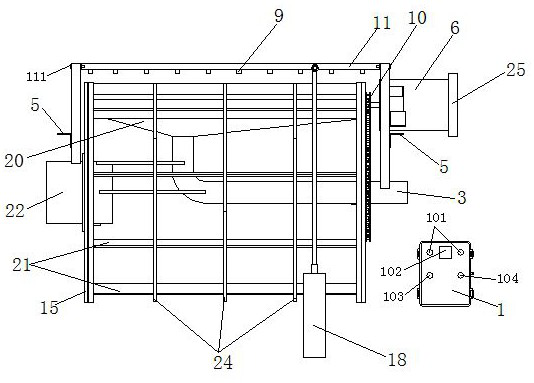
[0025] Such as Figure 1-9 As shown, the automatic backwash submersible microfilter includes a drum, a backwash device and a mounting bracket.

[0026] The backwashing device includes a central pipe shaft, a high-stroke submersible pump 18, a nozzle installation pipe 11, a nozzle 9, a dirt bucket 20 and a transmission mechanism. The central pipe shaft is a stainless steel pipe, and concentric The water inlet pipe 22 and the sewage pipe 3 are separated by a certain distance as the water outlet, and are welded together by the connecting bar 23. The sewage bucket 20 and the nozzle installation pipe 11 are installed directly ...


PUM


Abstract

The invention discloses an automatic-backwashing sedimentation type micro-filter, comprising a rotary drum, a backwashing device and a mounting bracket, wherein the backwashing device comprises a central pipe shaft, a high-stroke submersible pump, a spray head mounting pipe, spray heads, a sewage receiving hopper and a transmission mechanism; the central pipe shaft is a stainless steel pipe, and a water inlet pipe and a sewage discharge pipe which are concentric are respectively arranged on the left side and the right side of the central pipe shaft; a gap with a certain width is formed between the water inlet pipe and the sewage discharge pipe and functions as a water outlet; the water inlet pipe and the sewage discharge pipe are welded together via a connecting strip to form an integral body; the sewage receiving hopper and the spray head mounting pipe are mounted right above the central pipe shaft; the transmission mechanism is mounted on the sewage discharging pipe located on the right side of the central pipe shaft; the rotary drum is mounted on the central pipe shaft; the central pipe shaft serves as a shaft the rotary drum; the sewage receiving hopper is in a funnel shape, the lowest part of the sewage receiving hopper is connected and communicated with a blow-off pipe, and the spray head mounting pipe is mounted right above the sewage receiving hopper; and the spray head mounting pipe is a pipe with two closed ends and is fixed on left and right fixed pipes, a plurality of holes are formed right below the spray head mounting pipe for mounting the spray heads, and a hole is formed in the side surface for mounting a water supply pipe which is to be connected and communicated with the high-stroke submersible pump.

Description

technical field [0001] The invention belongs to the technical field of aquaculture water treatment equipment, and in particular relates to an automatic backwash submersible microfilter. Background technique [0002] The industrial recirculating aquaculture method is gradually accepted by people and more and more applied to production practice due to its advantages of environmental friendliness, energy saving and water saving. The factory recirculating aquaculture system (RAS) can provide a controlled environment, the size of the system is not limited by environmental conditions, the growth rate of aquaculture products can be controlled, and the output can even be predicted. Compared with traditional breeding methods, the recirculating aquaculture production method can save 90-99% of water consumption and 99% of land occupation per unit of production, and hardly pollute the environment. Water treatment is the most important part of the industrial recirculating aquaculture me...

Claims


Application Information

Patent Timeline
Patent Type & Authority Applications(China)
IPC IPC(8): B01D36/02B01D35/16
CPCB01D35/16B01D36/02
Inventor 侯宗元
Owner 广西木壳科技有限公司
Learn More