
High vertical grid type offshore wind power foundation anti-scouring system and method

An offshore wind power and grid technology, applied in wind power generation, infrastructure engineering, wind turbines, etc., can solve the problems of general protection effect and high construction cost, and achieve the effect of strengthening strength, avoiding collapse and increasing stiffness.

Pending Publication Date: 2021-08-03
HUANENG CLEAN ENERGY RES INST
View PDF0 Cites 3 Cited by
  • Summary
  • Abstract
  • Description
  • Claims
  • Application Information

AI Technical Summary

Problems solved by technology

Traditional anti-scouring measures for offshore wind power foundations generally have the problems of high construction costs and general protection effects

Method used


Image

  • High vertical grid type offshore wind power foundation anti-scouring system and method
  • High vertical grid type offshore wind power foundation anti-scouring system and method

Examples


Embodiment 1

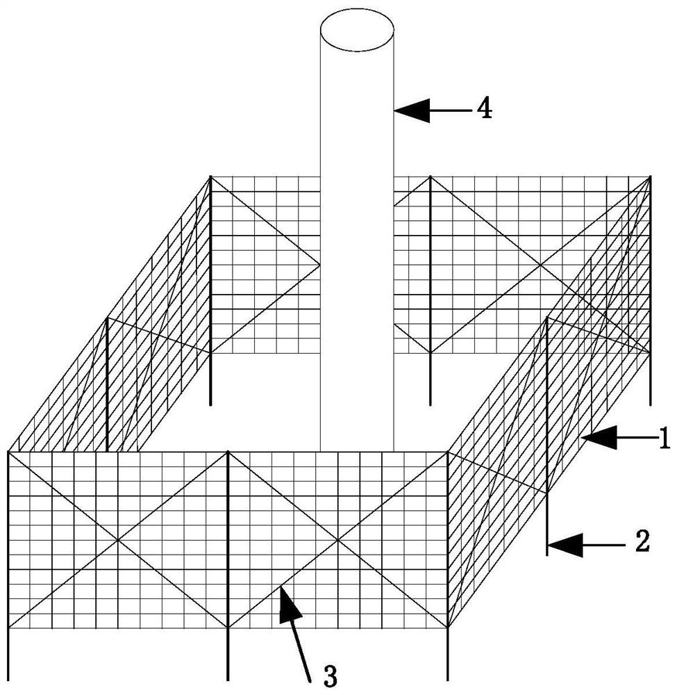
[0031] see figure 1 As shown, the present invention provides an anti-scouring system for offshore wind power foundations in a high vertical grid format, including grids 1, columns 2, reinforced connecting ribs 3 and offshore wind power foundations 4;

[0032] Several grids 1 are arranged around the offshore wind power foundation 4 , each grid 1 is vertically fixed by two uprights 2 , and each grid 1 is provided with two reinforcing connecting ribs 3 on its diagonal.

[0033] The grid 1 is in the shape of a rectangular net, made of corrosion-resistant metal material or high-strength fiber material, and its porosity is 10% to 50%.

[0034] The bottom edge of the grid 1 is close to the seabed surface.

[0035] Column 2 is a corrosion-resistant metal cylinder, buried in the seabed and fixed.

[0036] Reinforced connecting ribs 3 are corrosion-resistant metal connectors.

[0037] A plurality of grids are connected end to end and form a grid structure around the offshore wind pow...

Embodiment 2

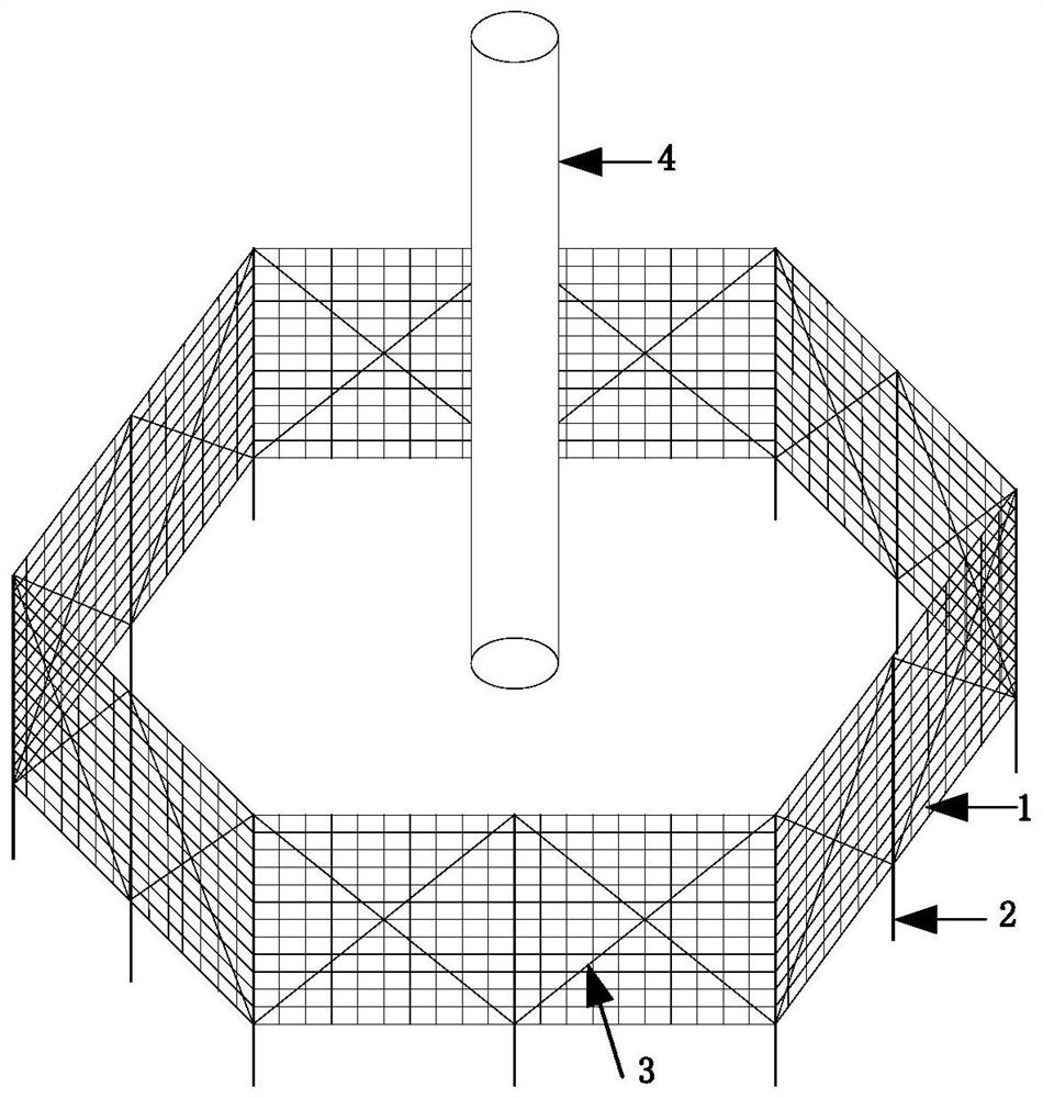
[0041] see figure 2 As shown, the second embodiment has the same structure as the first embodiment, but the shape of the grid cross section is different, and the shape of the grid cross section in this embodiment is a regular hexagon. The reason for this embodiment is that the protection range of a regular hexagon is greater than that of a square.

Embodiment 3

[0043] On the basis of Embodiment 1 or 2, according to the actual needs of the project, a multi-layer grid structure can be arranged around the offshore wind power foundation 4 to enhance the protection effect. The cross-sections of the multi-layer grid structure are the same or different. When they are different, the flow direction of seawater and sediment passing through different layers of grids 1 can be changed, the flow velocity of sediment can be further reduced, and the anti-scouring effect can be improved.


PUM


Abstract

The invention provides a high vertical grid type offshore wind power foundation anti-scouring system and method. The high vertical grid type offshore wind power foundation anti-scouring system comprises a plurality of grids, wherein each grid is vertically fixed between two stand columns, the multiple grids are connected end to end and form a grid type structure around a offshore wind power foundation, each grid is rectangular, and two reinforcing connecting ribs are arranged on the diagonal line of each grid. According to the high vertical grid type offshore wind power foundation anti-scouring system, the flow speed of water flow is reduced through the grids, sediment close to the bottom layer of a seabed is blocked from flowing, and the foundation anti-scouring purpose is achieved; through the grid diagonal reinforcing connecting ribs, the connecting rigidity of a grid system is increased, and the situation that the system is scoured and collapsed by the water flow is avoided; through the grid type structure, the flow blocking strength of the grids is further enhanced, and the all-around basic anti-scouring effect can be provided in the ocean current environment with changeable flow directions.

Description

technical field [0001] The invention belongs to the technical field of wind power generation, and in particular relates to an anti-scouring system and method for a high vertical grid offshore wind power foundation. Background technique [0002] The surroundings of offshore wind power foundations are easily affected by seabed currents to form scour pits, which reduces the buried depth of foundations and affects the safe and stable operation of wind turbines. At present, the traditional anti-scouring measures for offshore wind power foundations are mostly to improve the anti-scouring capability by laying protective layers within the foundation range, such as laying stones, concrete blocks, sandbags, concrete hinge rows, etc. in the protection area; The water flow velocity in the protection area is used to achieve the purpose of anti-scouring, such as the protection of the front deflector of the foundation. Traditional anti-scour measures for offshore wind power foundations ge...

Claims


Application Information

Patent Timeline
Patent Type & Authority Applications(China)
IPC IPC(8): E02D27/42E02D27/52E02B3/26F03D13/25F03D80/00
CPCE02D27/425E02D27/52E02B3/26F03D13/25F03D80/00Y02A30/30Y02E10/727Y02E10/72
Inventor 张庆张立英郭辰李芊邵振州
Owner HUANENG CLEAN ENERGY RES INST
Learn More