Feeding mechanism and double-end chamfering equipment

A feeding and chamfering technology, which is applied in the direction of metal processing equipment, metal processing machinery parts, clamping, etc., can solve the problems of automatic feeding of pipes, etc., and achieve the effect of ingenious structural design, high degree of automation, and reduced wear

Pending Publication Date: 2021-08-03
荆州市天宇汽车配件有限公司
View PDF7 Cites 0 Cited by
  • Summary
  • Abstract
  • Description
  • Claims
  • Application Information

AI Technical Summary

Problems solved by technology

[0003] The purpose of the present invention is to provide a feeding mechanism and double-head chamfering equipment, aiming to solve the problem that the existing feeding mechanism cannot automatically load small-diameter and light-weight pipes

Method used


Image

  • Feeding mechanism and double-end chamfering equipment
  • Feeding mechanism and double-end chamfering equipment
  • Feeding mechanism and double-end chamfering equipment

Examples


Embodiment 1

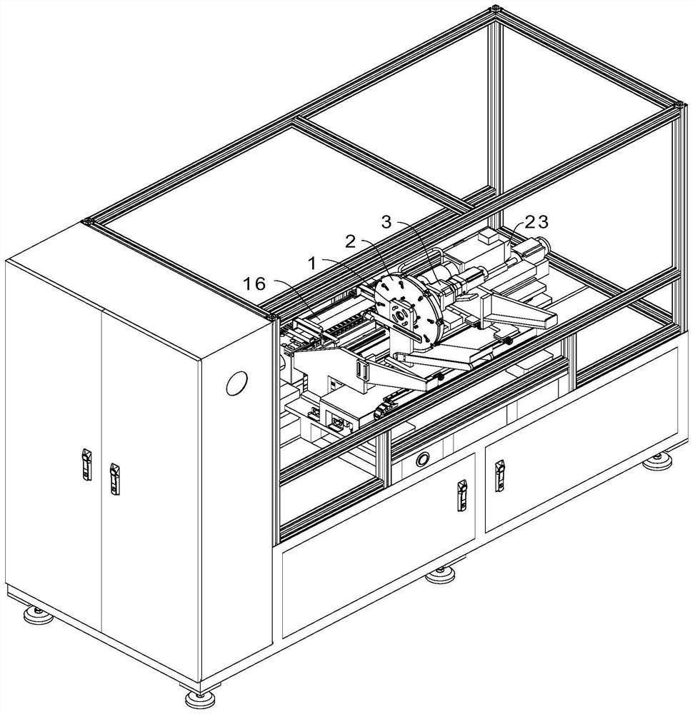
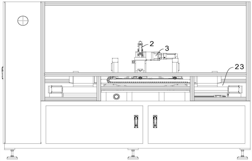
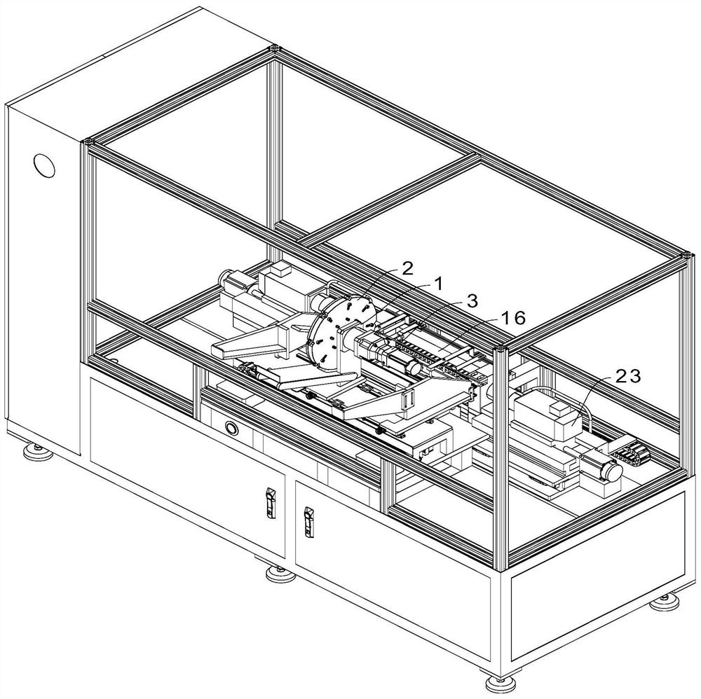
[0047] A double-head chamfering equipment, such as Figure 1 to Figure 11 As shown, a feeding mechanism is included, and the feeding mechanism includes a bracket 1, a feeding tray 2 rotated on the bracket 1, a rotary drive device 3 that drives the rotation of the loading tray 2, and the bracket 1 is formed with Feeding station 4, the feeding tray 2 is equipped with a plurality of hooks 5 and a plurality of tension springs 6, the hooks 5 can move in the radial direction of the feeding tray 2, and the tensioning The elastic force of the spring 6 acts on the hook body 5 and drives the hook body 5 close to the middle part of the feeding tray 2, and the hook body 5 is close to the outer edge 8 of the feeding tray (referring to the peripheral side wall of the feeding tray 2) One end of one end is formed with a hook 7, and a clamping gap is formed between the hook 7 and the outer edge 8 of the feeding tray. The bracket 1 is provided with a convex portion 9, and the convex portion 9 i...

Embodiment 2

[0060] A kind of double-head chamfering equipment, the difference from Embodiment 1 is that the reference Figure 12 , the feeding tray 2 is integrally formed, the side wall is formed with a concave cavity 26, the convex part 9 is installed and fixed on the fixed shaft 1b and is located in the concave cavity 26, the chute 11 and the The concave cavities 26 are connected, and the end of the hook body 5 close to the middle of the feeding tray 2 enters the concave cavity 26 , the structure is simpler, and the feeding function can also be realized at the same time.


PUM


Abstract

The invention relates to the technical field of feeding and chamfering equipment, and discloses a feeding mechanism and double-end chamfering equipment. The feeding mechanism comprises a support, a feeding disc rotationally arranged on the support and a rotation driving device for driving the feeding disc to rotate, a feeding station is formed on the support, and a plurality of hook bodies and a plurality of tension springs are installed on the feeding disc. The hook bodies can move in the radial direction of the feeding disc, the elastic force of the tension springs acts on the hook bodies and drives the hook bodies to be close to the middle of the feeding disc, hook parts are formed at the ends, close to the outer edge of the feeding disc, of the hook bodies, clamping gaps are formed between the hook parts and the outer edge of the feeding disc, and protrusion parts are arranged on the support. The protrusion parts are used for pushing the hook bodies to be away from the middle of the feeding disc after making contact with the hook bodies to enlarge the clamping gaps. The feeding mechanism is good in feeding effect, and the double-end chamfering equipment is ingenious in design, high in automation degree, capable of saving manpower, good in chamfering machining effect and high in production efficiency.

Description

technical field [0001] The invention relates to the technical field of feeding and chamfering equipment, in particular to a feeding mechanism and double-head chamfering equipment. Background technique [0002] Automobile pipes and automobile oil pipes are indispensable parts in automobile production. Due to their small diameter and light weight, in their chamfering processing, the existing chamfering processing equipment needs to be manually loaded, while using the existing technology The steel pipe feeding mechanism (such as setting a placement groove that fits the two ends of the steel pipe, the steel pipes are placed in the placement groove one by one, the placement groove has an oblique part and a vertical part, and the self gravity of the steel pipe is used when chamfering One by one falling and being chamfered) cannot realize one by one feeding or the feeding effect is not good (it is light in weight, and it cannot fall smoothly when the friction force between it and t...

Claims


Application Information

Patent Timeline
Patent Type & Authority Applications(China)
IPC IPC(8): B23D79/00B23Q7/00B23Q3/06
CPCB23D79/00B23Q7/00B23Q3/06
Inventor 王书杰刘先洲杨波舒武星
Owner 荆州市天宇汽车配件有限公司
Why Eureka
Try Eureka