Eureka AIR delivers breakthrough ideas for toughest innovation challenges, trusted by R&D personnel around the world.

Automatic gate removing equipment

A nozzle and equipment technology, applied in the field of automatic nozzle equipment, to achieve the effect of high level of flexibility, controllable vibration and good rigidity

Pending Publication Date: 2021-08-03
五羊—本田摩托(广州)有限公司
View PDF0 Cites 1 Cited by
  • Summary
  • Abstract
  • Description
  • Claims
  • Application Information

AI Technical Summary

Problems solved by technology

[0003] The purpose of the present invention is to provide an automatic dewatering device, aiming to solve the problems existing in the existing dewatering slag bag technology

Method used


Image

  • Automatic gate removing equipment
  • Automatic gate removing equipment
  • Automatic gate removing equipment

Examples


Embodiment Construction

[0028] In order to make the purpose, technical solutions and advantages of the embodiments of the present invention clearer, the technical solutions in the embodiments of the present invention will be clearly and completely described below in conjunction with the drawings in the embodiments of the present invention. Obviously, the described embodiments It is a part of embodiments of the present invention, but not all embodiments. The components of the embodiments of the invention generally described and illustrated in the figures herein may be arranged and designed in a variety of different configurations.

[0029] Accordingly, the following detailed description of the embodiments of the invention provided in the accompanying drawings is not intended to limit the scope of the claimed invention, but merely represents selected embodiments of the invention. Based on the embodiments of the present invention, all other embodiments obtained by persons of ordinary skill in the art wi...


PUM


Abstract

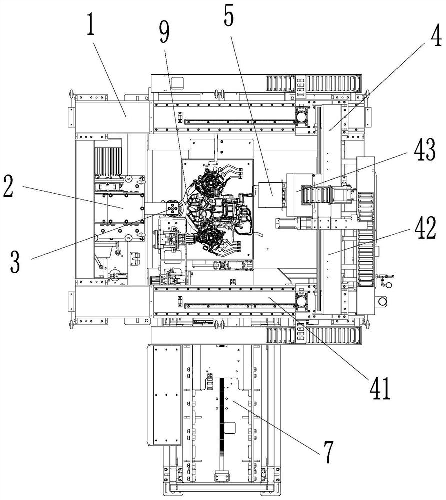
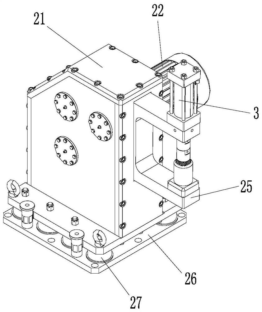
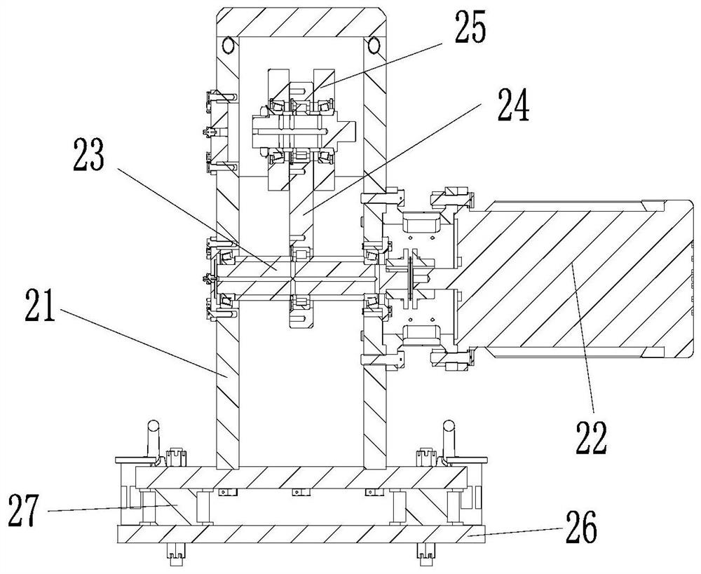
The invention provides automatic gate removing equipment. The automatic gate removing equipment comprises a first rack, a super-vibration mechanism, a clamping mechanism, a three-axis servo mechanism and a pneumatic hammer, wherein the super-vibration mechanism comprises a shell, a first driving device, an eccentric shaft, a swing arm and a swing head; the shell is installed in the first rack, and a through hole is formed in one side wall of the shell; the two ends of the eccentric shaft are rotatably installed on the shell; an eccentric part is arranged on the eccentric shaft, and one end of the swing arm is assembled at the eccentric part of the eccentric shaft; the other end of the swing arm is rotatably installed at one end of the swing head, and the other end of the swing head extends out of the through hole, and then is connected with the clamping mechanism; the middle of the swing head is rotatably installed on the shell; the first driving device is in driving connection with one end of the eccentric shaft, and used for driving the eccentric shaft to rotate, and the three-axis servo mechanism is installed on the top of the first rack; and the pneumatic hammer is installed on the three-axis servo mechanism. The invention aims to solve the problems existing in an existing gate and slag ladle removing technology.

Description

technical field [0001] The invention belongs to the technical field of casting equipment, and in particular relates to an automatic drain outlet equipment. Background technique [0002] In the production process of aluminum alloy die-casting products, in addition to the product body, along with the die-casting products, there are also necessary process designs such as material handle (injection part), nozzle, slag bag, and exhaust port. The parts produced in these processes are of great importance to the casting process. It is necessary in the medium, but it is redundant for the final product, and the material handle, nozzle and slag bag need to be removed. At present, there are several processing methods for removing the material shank, nozzle and slag bag. The first method is to use a hydraulic punch combined with a punching die. One set of punching dies, and it takes a long time to change the model, and the punching die needs to be switched every time the model is change...

Claims


Application Information

Patent Timeline
Patent Type & Authority Applications(China)
IPC IPC(8): B22D17/20B22D31/00
CPCB22D17/2076
Inventor 孙智英魏展聪朱永生邓金锋
Owner 五羊—本田摩托(广州)有限公司
Why Eureka
Eureka Blog
Learn More