Power factor correction rectifier for receiving end of wireless power transmission system

A power factor correction, wireless power transmission technology, applied in the output power conversion device, the conversion of AC power input to DC power output, electrical components and other directions, can solve the energy loss, high cost of switching tubes, circuit design and electromagnetic compatibility design difficulties And other issues

Active Publication Date: 2021-07-30
GUANGDONG UNIV OF TECH
View PDF6 Cites 0 Cited by
  • Summary
  • Abstract
  • Description
  • Claims
  • Application Information

AI Technical Summary

Problems solved by technology

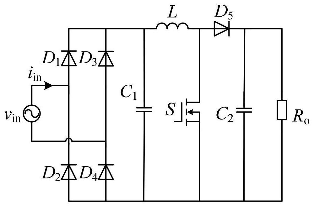
However, since the output voltage at the transmitting end of the wireless power transmission system is a high-frequency AC voltage, usually tens of thousands of hertz to megahertz, in order to achieve power factor correction, at the receiving end, namely figure 2 The frequency of the switching tube in the shown converter needs to reach its input voltage frequency, that is, hundreds or even thousands of times of the output voltage frequency of the transmitting end of the wireless power transmission system. In terms of current se

Method used


Image

  • Power factor correction rectifier for receiving end of wireless power transmission system
  • Power factor correction rectifier for receiving end of wireless power transmission system
  • Power factor correction rectifier for receiving end of wireless power transmission system

Examples


Embodiment Construction

[0039] This application provides a power factor correction rectifier at the receiving end of a wireless power transmission system, which is used to reduce the loss of switching devices, avoid the problem of potential parasitic parameters caused by high-frequency circuits, and realize the power factor correction of continuous current conduction, reducing harmonic wave effect.

[0040] In order to make the purpose, technical solutions and advantages of the embodiments of the present invention clearer, the technical solutions in the embodiments of the present invention will be clearly and completely described below in conjunction with the drawings in the embodiments of the present invention. Obviously, the described embodiments It is a part of embodiments of the present invention, but not all embodiments. Based on the embodiments of the present invention, all other embodiments obtained by persons of ordinary skill in the art without making creative efforts belong to the protectio...


PUM


Abstract

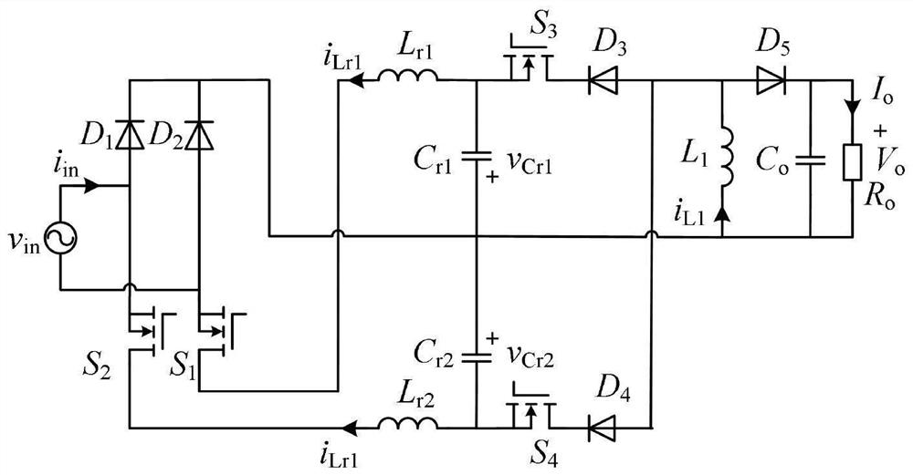
The invention discloses a power factor correction rectifier for a receiving end of a wireless power transmission system. The principle of inductance and capacitance resonance is utilized in the preceding stage, and the power factor correction technology of a medium-high frequency current continuous conduction mode is achieved. By reducing the switching frequency, the switching loss is reduced, and the influence of high-frequency parasitic parameters is reduced. The rear stage can be connected with various DC-DC converters, such as a Buck converter, a Buck-Boost converter and a Zeta converter, so that the output voltage can be flexibly controlled.

Description

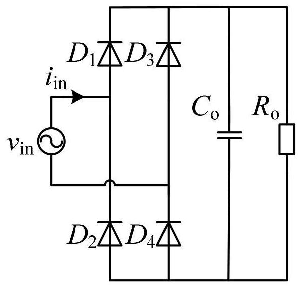
technical field [0001] The invention relates to the field of AC-DC power factor correction, in particular to a power factor correction rectifier at the receiving end of a wireless power transmission system Background technique [0002] With the maturity and wide application of power electronics technology and wireless power transmission technology, AC-DC rectifier converters have developed rapidly. At the same time, as users and manufacturers have higher and higher requirements on the power density of converters, the development of power electronics technology tends to be high frequency. Please refer to figure 1 , figure 1 The schematic diagram of the structure of the traditional full-bridge rectifier, the full-bridge rectifier in the prior art is composed of four uncontrollable diodes, resulting in extremely low input current power factor, which damages the power quality and the overall efficiency of the system, and brings Harmonic pollution and electromagnetic interfere...

Claims


Application Information

Patent Timeline
IPC IPC(8): H02M7/217H02M1/42
CPCH02M7/217H02M1/42Y02B70/10
Inventor 张桂东曾俊铭
Owner GUANGDONG UNIV OF TECH
Why Eureka
Try Eureka