Double-structure TBM hydraulic propelling system and double-structure TBM
A propulsion system and dual-structure technology, which is applied in the field of shield machines, can solve the problems that affect the tunneling efficiency, the processing time of the stuck machine is long, and the propulsion system cannot meet the construction needs.
- Summary
- Abstract
- Description
- Claims
- Application Information
AI Technical Summary
Problems solved by technology
Method used
Image

Examples
specific Embodiment 1
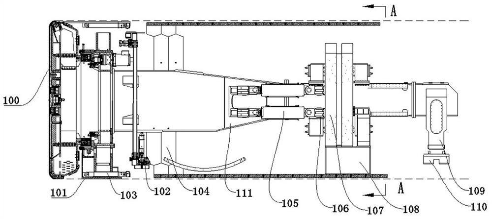
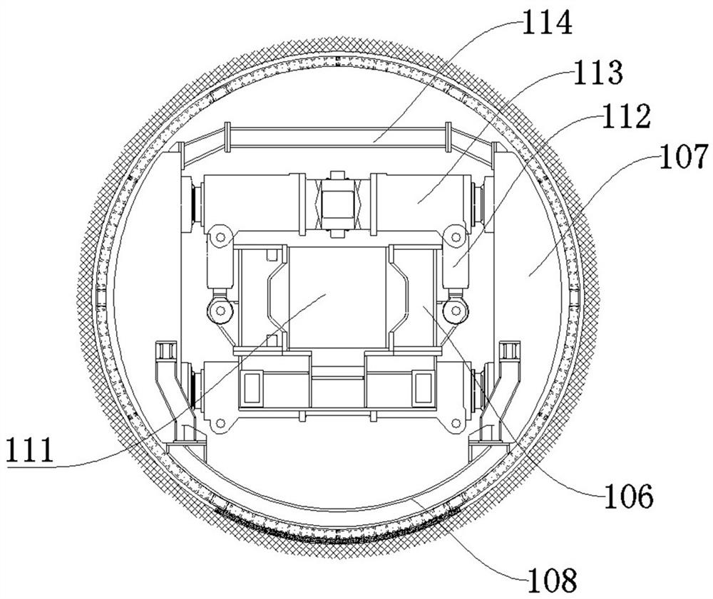
[0082] The structure of the dual-structure TBM provided in this embodiment is as follows Figure 1 to Figure 3 As shown, it includes a main beam 111, a shield body 101 is installed at the front end of the main beam 111, a cutter head 100 is arranged at the front end of the shield body 101, and a steel pipe sheet assembly machine 102 and a steel arch assembly machine are arranged on the main beam 111 at the rear side of the shield body 101 .
[0083] The main beam 111 is slidably equipped with a saddle frame 106, and the saddle frame 106 is equipped with a spreader shoe 107 through a shoe cylinder, and, as figure 2 As shown, the saddle frame support shoe 108 can be assembled at the bottom of the saddle frame 106. It should be noted that, in the shield body advancing excavation mode, the saddle frame support shoe 108 is fixedly connected with the two side support shoes 107 on the saddle frame 106, Thereby, the two sides of the boots 107 are formed as a whole, and, in order to ...
specific Embodiment 2
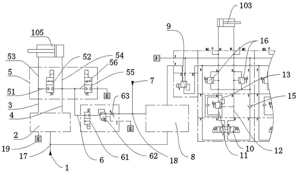
[0130] The main difference from Embodiment 1 is that in Embodiment 1, the main propulsion reversing valve is used as the main propulsion reversing device, and the propulsion pump source is controlled to provide hydraulic oil to the main propulsion rod cavity oil circuit, or to the main propulsion rodless The cavity oil circuit provides hydraulic oil. In this embodiment, the main propulsion reversing device can use a cartridge valve. When configuring the cartridge valve, select appropriate cartridge components to form a composite valve, which can meet the following requirements: The oil circuit supplies hydraulic oil, and at the same time connects the oil circuit of the main propulsion rodless chamber with the fuel tank, while the propulsion pump source supplies hydraulic oil to the oil circuit of the main propulsion rodless chamber, and at the same time communicates the oil circuit of the main propulsion rod chamber with the fuel tank.
[0131] Of course, in other embodiments,...
specific Embodiment 3
[0133] The main difference from Embodiment 1 is that in Embodiment 1, in the main propulsion hydraulic circuit, a floating oil circuit is provided between the main propulsion rodless chamber oil circuit and the main propulsion rod chamber oil circuit, so that the main propulsion hydraulic circuit It can make the main propulsion oil cylinder in a floating state. In this embodiment, the main propulsion reversing valve can be a Y-type reversing valve, and its middle position is a floating station, which can make the main propulsion rod chamber oil circuit and the main propulsion rodless chamber oil circuit communicate with the oil tank at the same time, thereby Keep the main propulsion cylinder in a floating state.
[0134] At this time, the excess hydraulic oil when the main propulsion cylinder is floating can directly flow back to the oil tank. When the hydraulic oil needs to be replenished during floating, the suction formed by the main propulsion cylinder can be used to direc...
PUM
 Abstract
Description
Claims
Application Information
 - R&D
- Intellectual Property
- Life Sciences
- Materials
- Tech Scout
- Unparalleled Data Quality
- Higher Quality Content
- 60% Fewer Hallucinations
Browse by: Latest US Patents, China's latest patents, Technical Efficacy Thesaurus, Application Domain, Technology Topic, Popular Technical Reports.
© 2025 PatSnap. All rights reserved.Legal|Privacy policy|Modern Slavery Act Transparency Statement|Sitemap|About US| Contact US: help@patsnap.com