
Automatic fixing frame for hoisting and transporting electromechanical equipment

A technology of electromechanical equipment and fixing frame, which is applied in the field of automatic fixing frame, which can solve the problems of small force bearing area, reduced service life of steel wire rope, long time, etc.

Inactive Publication Date: 2021-07-30
东莞市郭施杰电力设备有限公司
View PDF0 Cites 0 Cited by
  • Summary
  • Abstract
  • Description
  • Claims
  • Application Information

AI Technical Summary

Problems solved by technology

[0003] In construction work, it is usually necessary to use a crane to transport the electromechanical equipment to a high place, and the electromechanical equipment is often bound with steel wire ropes and hung on the hook of the crane, which will not only take more time to fix the equipment, but also The rope acts on the outer surface of the equipment. Due to the small stress area, the friction between the rope and the equipment will not only damage the surface of the equipment, but also reduce the service life of the wire rope after long-term use. Therefore, those skilled in the art provide a An automatic fixing frame for hoisting and transporting electromechanical equipment to solve the problems raised in the above-mentioned background technology

Method used


Image

  • Automatic fixing frame for hoisting and transporting electromechanical equipment
  • Automatic fixing frame for hoisting and transporting electromechanical equipment
  • Automatic fixing frame for hoisting and transporting electromechanical equipment

Examples


Embodiment Construction

[0020] The technical solutions in the embodiments of the present invention will be clearly and completely described below with reference to the accompanying drawings in the embodiments of the present invention. Obviously, the described embodiments are only a part of the embodiments of the present invention, but not all of the embodiments. Based on the embodiments of the present invention, all other embodiments obtained by those of ordinary skill in the art without creative efforts shall fall within the protection scope of the present invention.

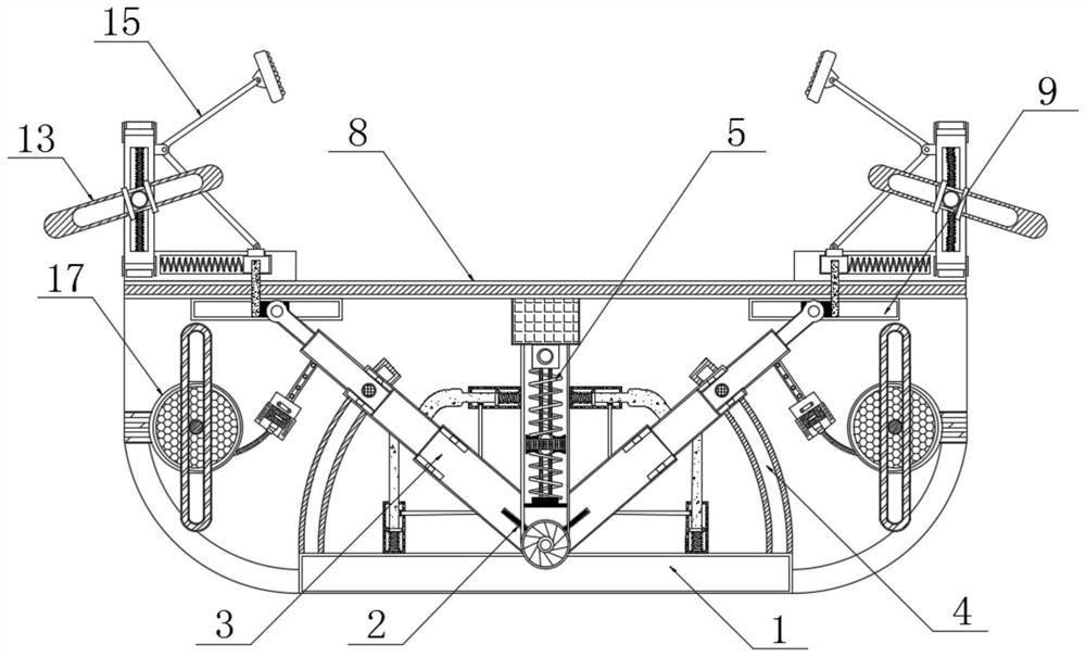
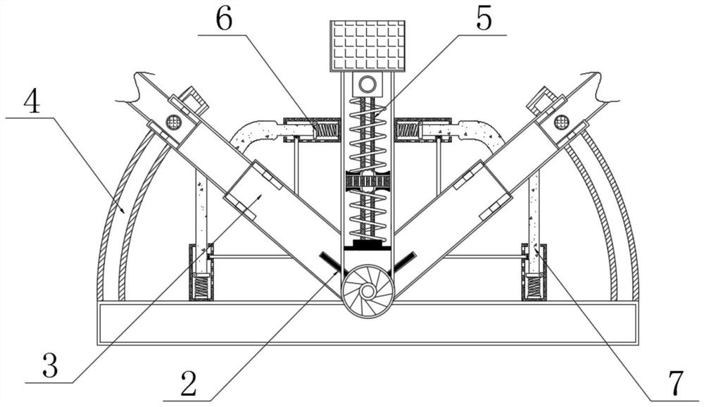
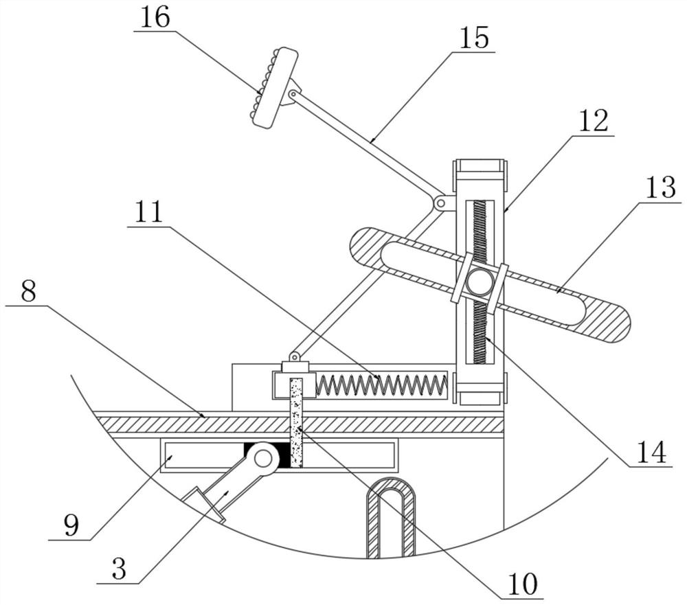
[0021] see Figure 1-5 , an automatic fixing frame for hoisting and transporting electromechanical equipment, including a placing seat 1, the inner bottom end of the placing seat 1 is movably connected with a special-shaped spring 2, and both sides of the special-shaped spring 2 are fixedly connected with a support rod 3, and the placing seat 1 The upper surface of the support rod 3 and the rear surface of the support rod 3 are fixedl...


PUM


Abstract

The invention relates to the technical field of electromechanical equipment, and discloses an automatic fixing frame for hoisting and transporting electromechanical equipment. A special-shaped spring is movably connected to the inner bottom end of a placing seat, supporting rods are fixedly connected to the two sides of the special-shaped spring, and sliding grooves are fixedly connected to the positions, located on the rear surfaces of the supporting rods, of the upper surface of the placing seat. An elastic rod is fixedly connected to the position, located on one side of the special-shaped spring, of the upper surface of the placing seat, a carrying plate is fixedly connected to the top end of the elastic rod, limiting plates are fixedly connected to the two ends of the upper surface of the carrying plate, the outer surfaces of the supporting rods are slidably connected into the sliding grooves through rotating shafts, and the sliding grooves are of an arc-shaped structure. Clamping plates automatically clamp equipment placed on the upper surface of the carrying plate, and then curved rods at the two ends are connected and fixed. According to the method, binding use of ropes is reduced, friction between the ropes and the surface of the equipment from causing loss of the ropes and the surface of the equipment can be effectively prevented, and the effect of saving time and labor is achieved.

Description

technical field [0001] The invention relates to the technical field of electromechanical equipment, in particular to an automatic fixing frame used for hoisting and transporting electromechanical equipment. Background technique [0002] Electromechanical equipment can be divided into three categories according to their uses, namely industrial electromechanical equipment, information electromechanical equipment and people's livelihood electromechanical equipment. Electromechanical equipment is widely used in daily life. Advanced electromechanical equipment can not only greatly improve labor productivity, but also reduce labor intensity. , improve the production environment, and can complete various complex tasks that cannot be done by manpower. [0003] In construction operations, it is usually necessary to use a crane to transport the electromechanical equipment to a high place, and the electromechanical equipment is often tied with a wire rope and then hung on the hook of t...

Claims


Application Information

Patent Timeline
IPC IPC(8): B66C1/42
CPCB66C1/42
Inventor 仲峰
Owner 东莞市郭施杰电力设备有限公司
Learn More