
Horizontal honing machine stroke structure

A honing machine and stroke technology, which is applied in the direction of honing machine tools, metal processing equipment, manufacturing tools, etc., can solve the problem that the overall operating efficiency cannot be improved well, the high-efficiency operating state cannot be well satisfied, and the overall operating efficiency is too affected major issues

Inactive Publication Date: 2021-07-30
南京森尔南精密机床有限公司
View PDF8 Cites 0 Cited by
  • Summary
  • Abstract
  • Description
  • Claims
  • Application Information

AI Technical Summary

Problems solved by technology

[0005] Aiming at the deficiencies of the prior art, the present invention provides a stroke structure of a horizontal honing machine, which has the advantages of improved machine tool efficiency, stable movement, no vibration during grinding, more than doubled reciprocating speed, and batch processing of holes with a diameter of Φ80 or less. Parts, greatly broadened the processing range and the accuracy of the hole, and solved the problem of not being able to ensure the efficiency of the machine tool, smooth movement, and no vibration during grinding. The stroke mechanisms of most honing machines are also placed horizontally, which affects the equipment. The overall operating efficiency cannot be improved very well, and the gravity has too much influence on the overall operating efficiency of the equipment, which cannot satisfy the problem of high-efficiency operating status.

Method used


Image

  • Horizontal honing machine stroke structure
  • Horizontal honing machine stroke structure
  • Horizontal honing machine stroke structure

Examples


Embodiment Construction

[0027]The following will clearly and completely describe the technical solutions in the embodiments of the present invention with reference to the accompanying drawings in the embodiments of the present invention. Obviously, the described embodiments are only some, not all, embodiments of the present invention. Based on the embodiments of the present invention, all other embodiments obtained by persons of ordinary skill in the art without making creative efforts belong to the protection scope of the present invention.

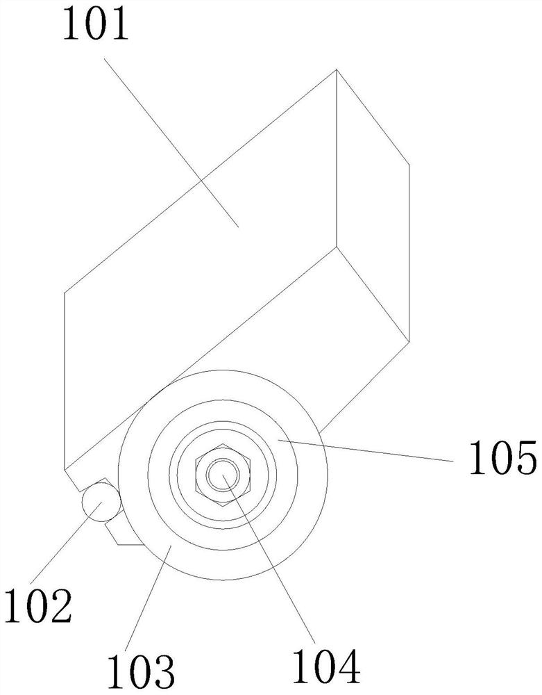
[0028] see Figure 1-5 , a horizontal honing machine stroke structure, including a buckle 1, the buckle 1 includes a clamping plate 101, a first rotating shaft 102, a first bearing 103, a first fixing screw 104 and a first engaging plate 105, the bottom of the clamping plate 101 A first rotating shaft 102 is movably connected, and a first bearing 103 is arranged in parallel on the right side of the first rotating shaft 102. A first engaging plate 105 is movably...


PUM


Abstract

The invention relates to the technical field of honing machines, and discloses a horizontal honing machine stroke structure which comprises a buckle. The buckle comprises a clamping plate, a first rotating shaft, a first bearing, a first fixing screw and a first clamping plate; and the first rotating shaft is movably connected to the lower part of the clamping plate. According to the horizontal honing machine stroke structure, through cooperative work of a supporting rod, a first notch, a first screw rod, a first gasket, a first nut, a first limiting plate, a second limiting plate, an inner connecting rod, a piston, an air cylinder, a third limiting plate, an air throttle, a first fixing rod and a first fixing base, the operation efficiency and precision of equipment are greatly improved, and the reciprocating speed is increased; the device is vertically placed, so that the influence of gravity is reduced, the reciprocating speed of a machine tool is greatly increased, and the machining range of the machine tool is greatly widened; and the machine tool can machine small holes with the diameters being smaller than phi 15 in batches and can machine parts with the diameters being smaller than phi 80 in batches, so that the machining range is greatly widened, and the precision of the holes is greatly improved.

Description

technical field [0001] The invention relates to the technical field of honing machines, in particular to a stroke structure of a horizontal honing machine. Background technique [0002] The grinding machine that uses the honing head to honing the surface of the workpiece is mainly used for honing the holes of the workpiece in the manufacturing industries such as automobiles, tractors, hydraulic parts, bearings, and aviation. There are two types of honing machines, vertical and horizontal, and the main shaft of the vertical honing machine The working stroke is short, suitable for honing cylinder and box holes, etc. The honing head inlaid with oil stone is driven by the vertical spindle to rotate, and at the same time it is driven by the hydraulic device to perform vertical reciprocating feed motion (see machine tool), horizontal The honing machine has a long working stroke and is suitable for honing deep holes with a depth of up to 3000 mm. The honing head placed horizontally...

Claims


Application Information

Patent Timeline
IPC IPC(8): B24B33/02B24B33/10
CPCB24B33/022B24B33/10
Inventor 王勇
Owner 南京森尔南精密机床有限公司
Learn More