Arm fracture rapid fixing splint for orthopedics department
A technology for fixing splints and arms. It is used in fractures, medical science, passive exercise equipment, etc. It can solve problems such as inconvenience, excessive time and energy, and achieve the effects of promoting blood circulation, relieving paralysis, and facilitating installation and disassembly.
- Summary
- Abstract
- Description
- Claims
- Application Information
AI Technical Summary
Problems solved by technology
Method used
Image
Examples
Embodiment 1
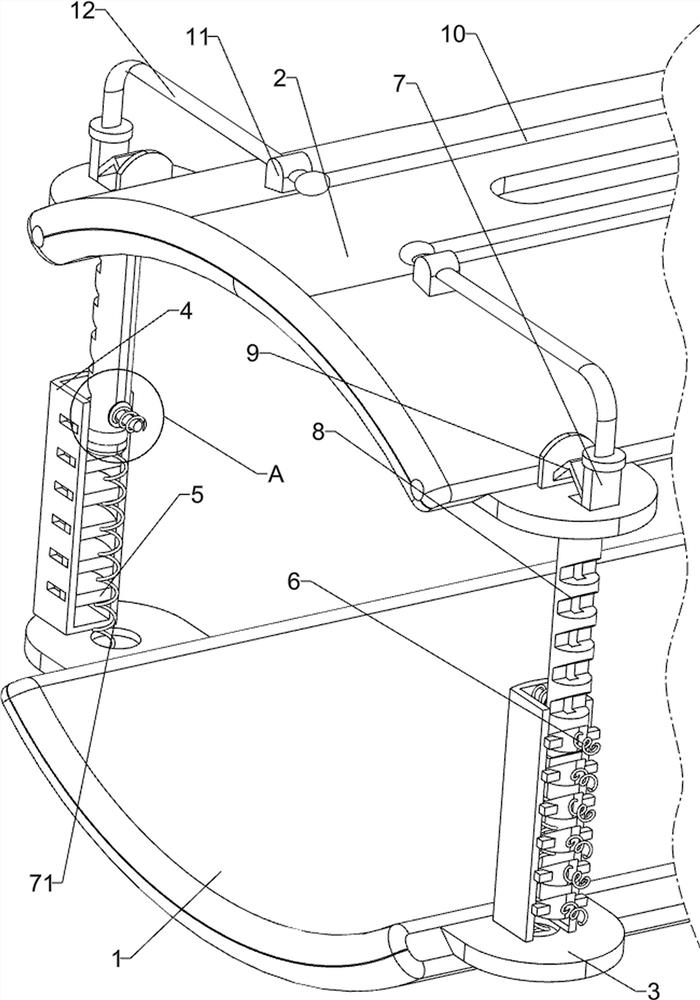
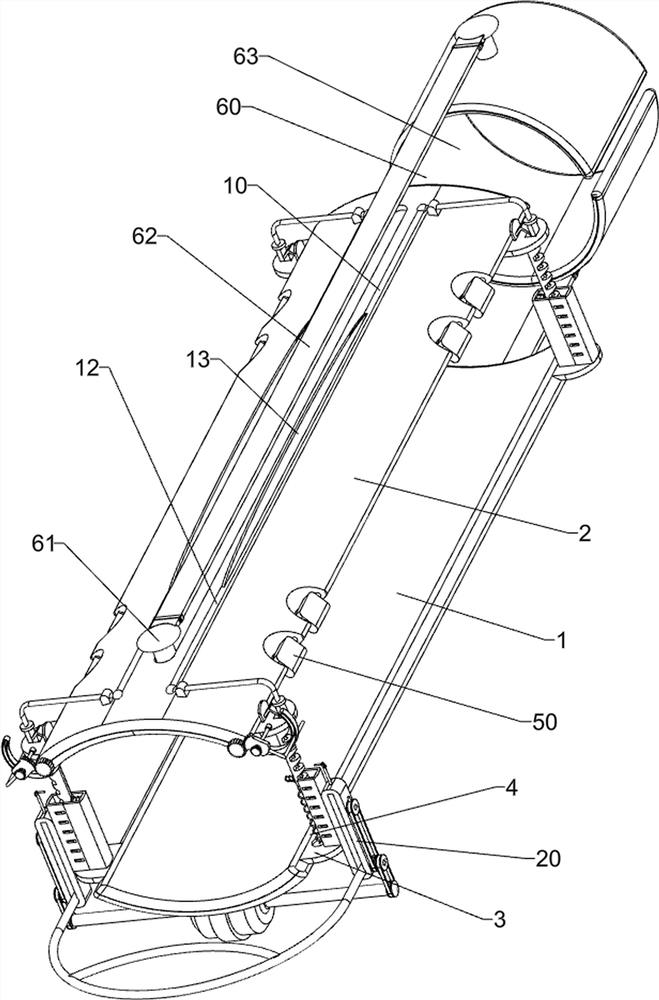
[0027] An orthopedic arm fracture fast fixing splint, such as Figure 1-2 As shown, including the lower splint 1, the upper pinch 2, the arc plate 3, the mounting frame 4, the block 5, the pressure spring 6, the connection slider 7, the recovery spring 71, the slot 8, the shrapnel 9, and the disassembly component 10, The arc plate 3 is provided with eight, and the upper side surfaces are connected between the inner side surfaces of the four arc plates 3, and the inner side surfaces of the four arc plates 3 corresponding to the lower side are connected to the lower splint 1, the lower arc plate. 3 The top of the 3 is connected to the mounting frame 4, and the inner wall of the mounting frame 4 is uniformly intervals having a plurality of pressure spring 6, and a block 5 is connected to the pressure spring 6, and the upper arc plate 3 slides a connection slider. 7, the connection slider 7 is connected to the bottom of the slot 8, and the groove 8 is mounted, and the groove 8 is conne...
Embodiment 2
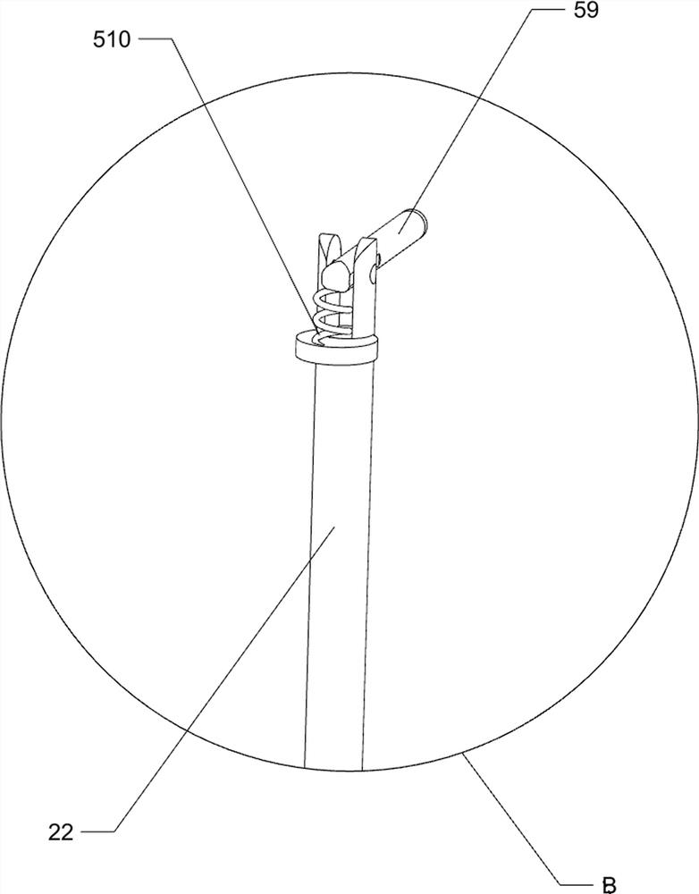
[0031] On the basis of Example 1, such as figure 1 and image 3 The active assembly 20 is also included, and the movable assembly 20 includes a bracket 21, a guide bar 22, a cushion spring 23, a pulley 24, a flat belt 25, a push rod 26, a lever 27, and a rail 28, and the left side corresponds. The outer wall of the two mounting frames 4 is connected to the rail 28, and the two rails 28 are slidably connected to the bracket 21, and the front and rear sides of the top and rear sides of the bracket 21 are connected to the guide bar 22, the guide bar 22 and the slide rail 28. The sliding connection, the bracket 21 and the slide rail 28 are connected between the buffer spring 23, and the sidedly symmetrical rotary connection of the outer side surface of the slide rail 28 has two pulley 24, and the two pulley 24 has a flat belt 25, a flat belt. On 25, two push rods 26 are connected, and both the front and rear sides of the bracket 21 are connected to both sides, and the lever 27 cooperat...
Embodiment 3
[0035] On the basis of Example 2, such as Figure 4 As shown, there is also a guide assembly 40, and the guide assembly 40 includes a finite bit rod 41, a reset spring 42, and a disk 43, and the inner wall of the mounting frame 4 is connected to the finite rod 41, and the sliding type connection on the limit rod 41 has a disk 43. A reset spring 42 is connected between the disc 43 and the mounting frame 4.
[0036] The slot rod 8 can be guided by the limit rod 41, so that the slot rod 8 can move smoothly, and it is possible to prevent the slot rod 8 from being shifted, and when the slot rod 8 moves inward, the disc 43 can be moved inward, When the reset spring 42 is compressed, after the grip 13 is released, the disc 43 can be reset to the outside, and the disk 43 can be reset to the outside to push the slot 8 outward movement; Thus, the slot rod 8 can be directed by the guide assembly 40, so that the slot rod 8 can move smoothly, and it is possible to prevent the slot 8 from being ...
PUM
 Abstract
Description
Claims
Application Information
 - R&D Engineer
- R&D Manager
- IP Professional
- Industry Leading Data Capabilities
- Powerful AI technology
- Patent DNA Extraction
Browse by: Latest US Patents, China's latest patents, Technical Efficacy Thesaurus, Application Domain, Technology Topic, Popular Technical Reports.
© 2024 PatSnap. All rights reserved.Legal|Privacy policy|Modern Slavery Act Transparency Statement|Sitemap|About US| Contact US: help@patsnap.com


