
Bourdon tube torque measuring device and test method thereof

A torque measurement and spring tube technology, applied in the field of spring tube torque measurement devices, can solve the problems of waste of resources, non-universal use, poor economic benefits, etc., and achieve the effects of simple overall structure, improved use efficiency, and accurate data measurement

Active Publication Date: 2021-07-27
SHANGHAI SATELLITE ENG INST
View PDF20 Cites 2 Cited by
  • Summary
  • Abstract
  • Description
  • Claims
  • Application Information

AI Technical Summary

Problems solved by technology

[0003] The patent document CN101639392 discloses a torque measuring device of a non-inserting shaft torque measuring device and a method for measuring torque using the measuring device. The above-mentioned solution has the following technical problems: since it is necessary to measure the deformation of the torsion bar to Indirect measurement of torque value, if the input torque value exceeds the measurement range, it is easy to twist the torsion bar and damage the torque measurement device; if the input torque is too small, it is difficult to deform the torsion bar sensitively, thus affecting the torque measurement Sensitivity and precision of the device
[0004] However, due to the different types and specifications of the spring tubes, and the torque of the spring tubes under different angles is also different, the current conventional torque measuring tool is not universal for spring tubes of different specifications, so the spring tubes of different specifications and models are measured. It is necessary to replace the corresponding tooling from time to time, the work efficiency is low, the economic benefit is poor, and resources are wasted

Method used


Image

  • Bourdon tube torque measuring device and test method thereof
  • Bourdon tube torque measuring device and test method thereof
  • Bourdon tube torque measuring device and test method thereof

Examples


Embodiment Construction

[0030] The present invention will be described in detail below in conjunction with specific embodiments. The following examples will help those skilled in the art to further understand the present invention, but do not limit the present invention in any form. It should be noted that those skilled in the art can make several changes and improvements without departing from the concept of the present invention. These all belong to the protection scope of the present invention.

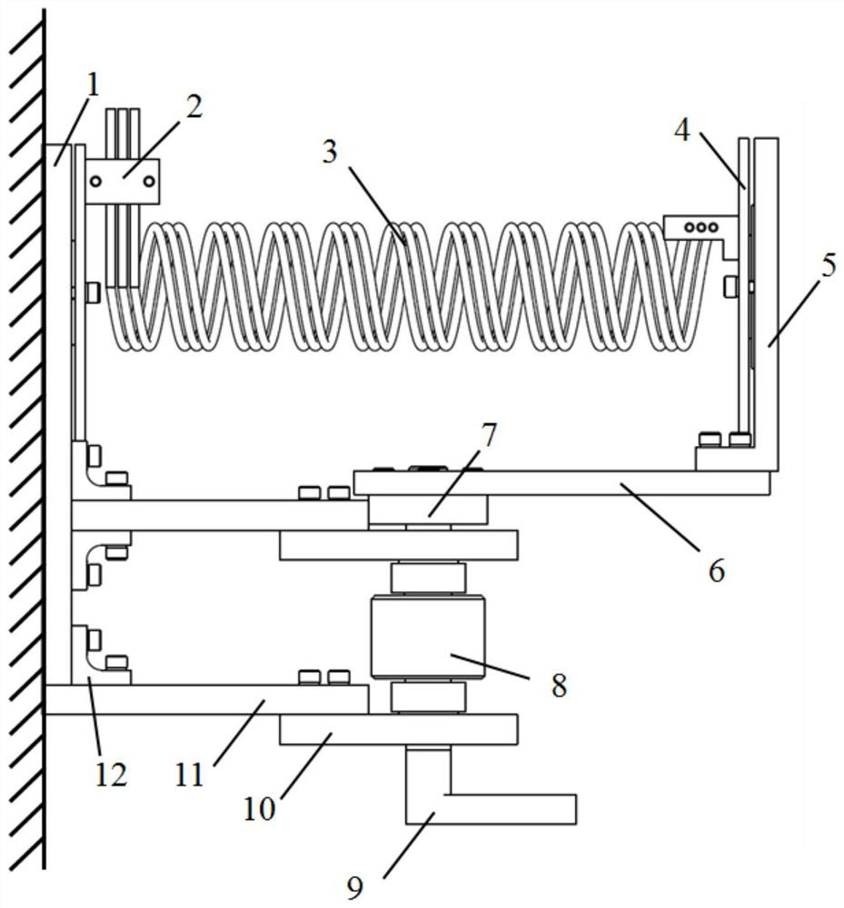
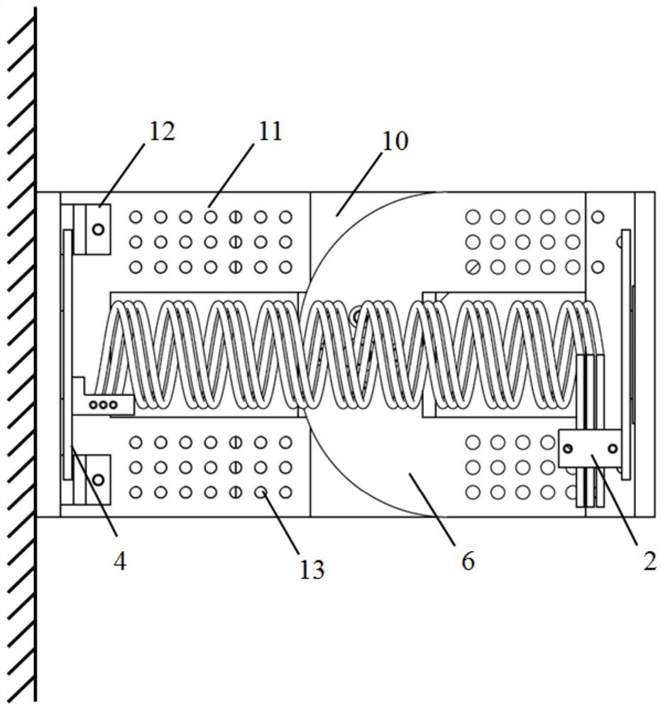
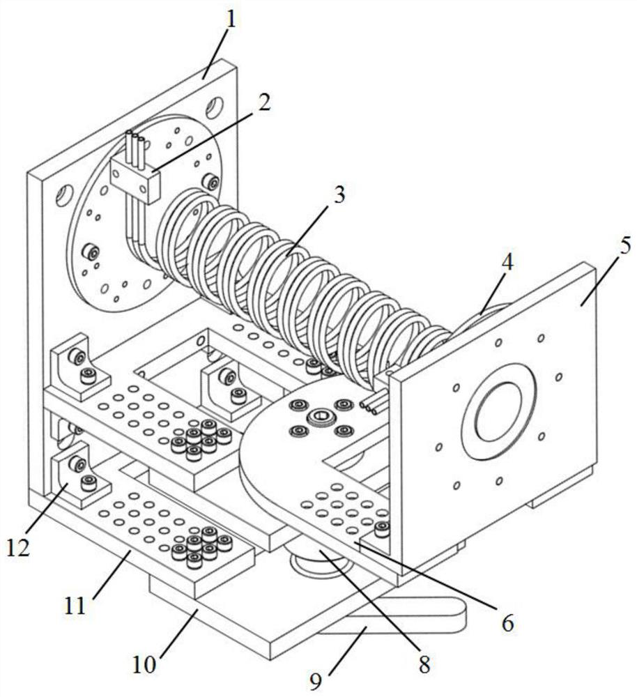
[0031] Such as Figure 1 to Figure 3 As shown, a spring tube torque measuring device and its test method of the present invention, the mechanism includes a bottom base 1, a clamp 2, a spring tube 3, a rotating table 4, a top base 5, a horizontal support plate 6, a rotating shaft 7, a torque Sensor 8, handle 9, lower support plate 10, upper support plate 11, deck 12, screw 13. The bottom base 1 is fixed on the vertical table, and the spring tube 3 is fixed on the turntable 4 through clamping 2. The turn...


PUM


Abstract

The invention provides a bourdon tube torque measuring device and a test method thereof. The bourdon tube torque can be measured through the adjustable torque measuring device, and the bourdon tube torque measuring device comprises a bourdon tube, a base, a rotating table, supporting plates, a clamp, a torque sensor, a rotating shaft, a handle, a clamp seat, a screw, a spring washer and a flat washer; the bottom base is fixed on a vertical table top; the bourdon tube is fixed on the rotating table through the clamp, the rotating table is in bearing fit with the base, the bottom base is respectively connected with the two upper supporting plates and is fixed through the clamp seat, two ends of a torque sensor shaft are connected with the rotating shaft through keys, two ends of the rotating shaft are respectively in bearing fit with the two lower supporting plates, and the upper supporting plates and the lower supporting plates are connected through screws. A top base is connected to one end of the rotating shaft through the horizontal supporting plate, and the other rotating shaft is connected with the handle. According to the invention, a solution is provided for measuring the torques of bourdon tubes with different models and specifications and different angle directions; and data measurement is accurate, operation is easy and convenient, the overall structure is simple, and needed hardware resources are fewer.

Description

technical field [0001] The invention relates to the field of torque measurement, in particular to a spring tube torque measurement device and a test method thereof. Background technique [0002] The torque measuring device in the prior art mainly includes a strain gauge sensor and a torsion bar. The method for measuring the torque by using the measuring device is: if it is necessary to measure the static torque, one end of the torsion bar is connected with the tested piece and placed on the tested piece. Rotate under the drive of the torsion bar, and the other end is fixed, so that the small deformation of the torsion bar under the action of the input torque is measured by the strain sensor, and the torque value is measured through signal conversion; if it is necessary to measure the dynamic torque, connect one end of the torsion bar with the measured The parts are connected and rotated under the drive of the input torque, and the other end rotates freely, so the torque valu...

Claims


Application Information

Patent Timeline
Patent Type & Authority Applications(China)
IPC IPC(8): G01L5/00G01M13/00
CPCG01L5/0042G01M13/00
Inventor 周春华郑鸣轩叶子龙尹永康熊良磊贾奥男茅建伟申军烽
Owner SHANGHAI SATELLITE ENG INST
Learn More