Alignment turnover device for electric vehicle accessory machining
A flipping device, electric vehicle technology, applied in auxiliary devices, metal processing equipment, manufacturing tools, etc., can solve the problems of troublesome operation, large space occupation, and imprecise structure, and achieve the effect of convenient welding
- Summary
- Abstract
- Description
- Claims
- Application Information
AI Technical Summary
Problems solved by technology
Method used
Image


Examples
Embodiment 1
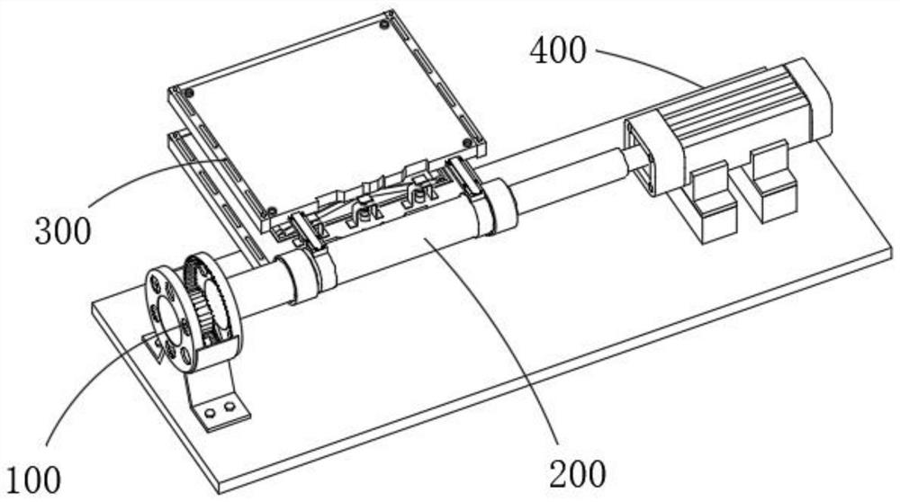
[0043] combine figure 1 ,2 , 3 and 4, the present invention provides a counter-position turning device for electric vehicle parts processing, including a driving device 100, a rotating mechanism 200, a lifting device 300 and a clamping device 400, and the driving device 100 includes a support frame 110 1. Turntable one 120 fixed on one side of the support frame 110, 130 installed on the outside of the first turntable 120, second turntable 140 fixed on the other side of the support frame 110, rotating gear one 150 installed on the inside of the support frame 110 and installation The second gear 160 is rotated inside the support frame 110, the rotating mechanism 200 is installed on one end of the driving device 100, the lifting device 300 is installed on the side of the rotating mechanism 200, the clamping device 400 is arranged on the front end of the rotating mechanism 200, The first rotating tooth 150 meshes with the sawtooth on the inner side of the rotating disk 120, the se...
Embodiment 2
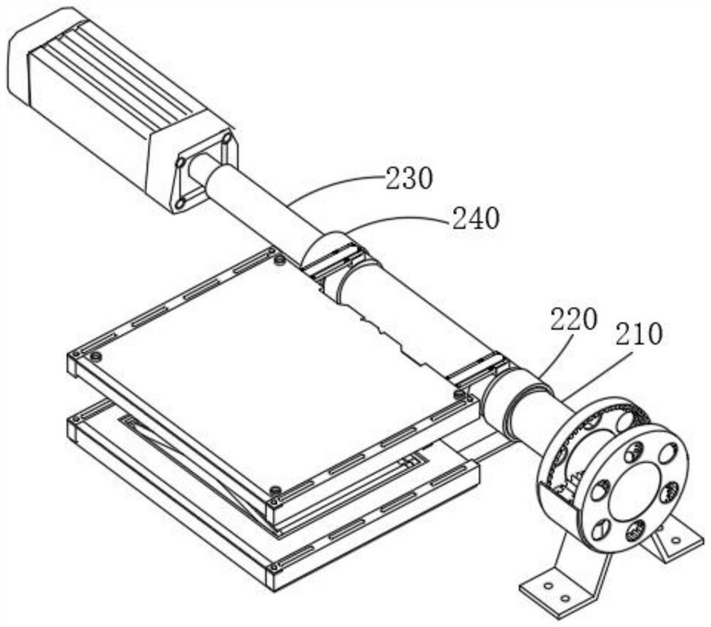
[0046] combine Figure 5 and 6 As shown, on the basis of Embodiment 1, the lifting device 300 includes an upper connecting plate 310 installed on the outside of the fixing member 220, a limiting platform 320 connected to one end of the upper connecting plate 310, and fixed on both sides of the limiting platform 320. The limit frame 330 on the side, the lower connection plate 340 fixed on the bottom of the fixed ring 240, the fixed platform 350 connected to one end of the lower connection plate 340, the shock absorber 360 installed on the top of the fixed platform 350, and the inner side of the fixed platform 350 The lifting bracket 370 and the installation top plate 380 installed on the upper end of the lifting bracket 370, the worker can push the lifting bracket 370 installed on the inside of the fixed platform 350 to realize the rise and fall of the installation top plate 380, and the limit frame 330 is set to facilitate the positioning of the limit platform 320 It is fixed...
Embodiment 3
[0048] combine Figure 7 As shown, in the above embodiment, the clamping device 400 includes an extension rod 410, an air guide rod 420 fixed on the outside of the extension rod 410, a piston sleeve 430 installed inside the air guide rod 420, and a piston sleeve installed on the piston sleeve. The limit rod 440 in the cylinder 430, the connecting seat 450 installed on the front end of the piston sleeve 430, the movable buckle 460 installed on one end of the connecting seat 450, the rotating shaft 470 passing through the movable buckle 460 and the clamping joint installed outside the rotating shaft 470 480, the air pump uses the extension rod 410 to deliver the air pressure to the inside of the piston sleeve 430 through the air guide rod 420, and the air pressure pushes the piston inside the piston sleeve 430, thereby pulling the limit rod 440 to move forward, and then driving the snap joint 480 outward Extend, so that the clamp joint 480 passes through the long shaft 230 and c...
PUM
 Abstract
Description
Claims
Application Information
 - Generate Ideas
- Intellectual Property
- Life Sciences
- Materials
- Tech Scout
- Unparalleled Data Quality
- Higher Quality Content
- 60% Fewer Hallucinations
Browse by: Latest US Patents, China's latest patents, Technical Efficacy Thesaurus, Application Domain, Technology Topic, Popular Technical Reports.
© 2025 PatSnap. All rights reserved.Legal|Privacy policy|Modern Slavery Act Transparency Statement|Sitemap|About US| Contact US: help@patsnap.com