Hydraulic filling valve assembly and hydraulic assembly having filling valve assembly

A technology for filling valves and components, applied in servo motor components, presses, manufacturing tools, etc., can solve problems such as consumption and high consumption

Pending Publication Date: 2021-07-23
ROBERT BOSCH GMBH
View PDF0 Cites 0 Cited by
  • Summary
  • Abstract
  • Description
  • Claims
  • Application Information

AI Technical Summary

Problems solved by technology

This is to be set sufficiently pressure-resistant for the mentioned pressure ranges, but this is expensive
[0003] Furthermore, fixed conventional filling valves on large presses are complex to construct

Method used


Image

  • Hydraulic filling valve assembly and hydraulic assembly having filling valve assembly
  • Hydraulic filling valve assembly and hydraulic assembly having filling valve assembly

Examples


Embodiment Construction

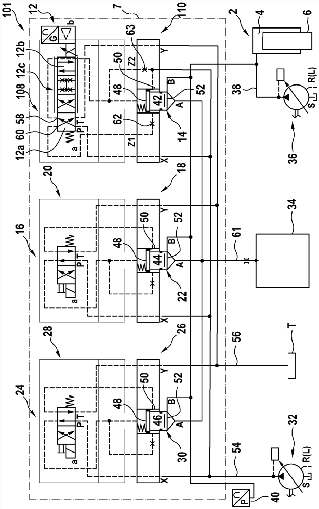
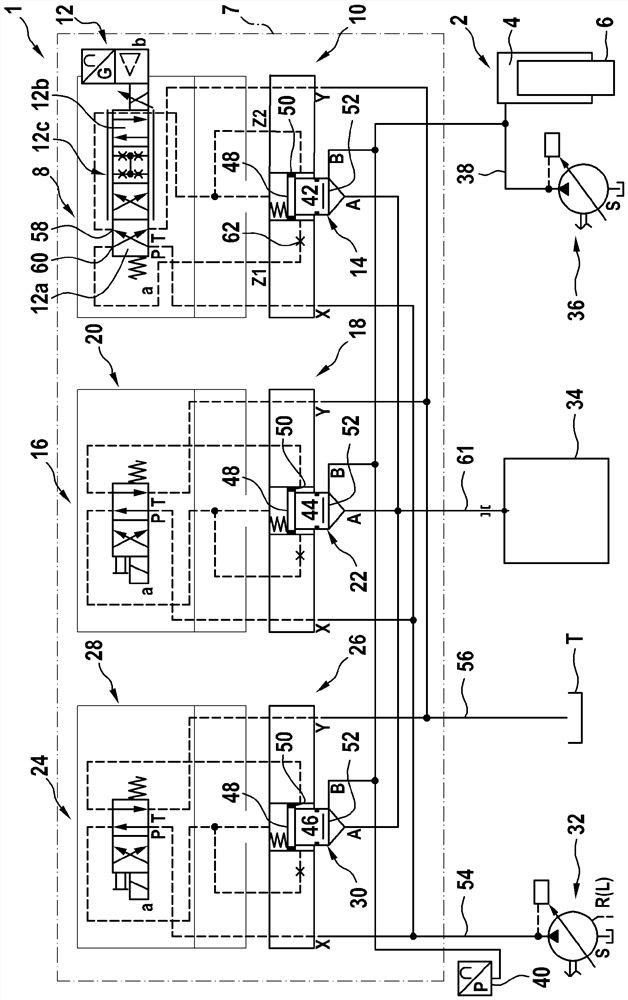
[0058] figure 1 A hydraulic line diagram of a large pressure machine of the first embodiment is shown. The large press has one or at least one hydraulic cylinder 2 having a pressure chamber 4, the pressure chamber being locally limited by the piston 6. In the illustrated embodiment, the gravity acceleration G acts on the piston 6, so that the gravity acceleration allows the piston to accelerate the direction of ziehkissen (not shown) to form a fast stroke, wherein the pressure chamber 4 is increased. .

[0059] In order to control the pressure chamber 4 and release the pressure medium from the pressure chamber 4, the pressure chamber can be fluidly coupled through the valve 8, 16, 24 and the Treated pressure medium container or pressure medium memory 34.

[0060] In order to apply the pressure of the hydraulic cylinder 2, the large pressure machine has a high-pressure medium source 36 in an open hydraulic circuit, which is fluidly coupled to the pressure chamber 4 through the wor...


PUM


Abstract

The invention relates to a hydraulic filling valve assembly for re-drawing a pressure medium into a pressure chamber of a hydraulic cylinder and for releasing the pressure medium therefrom, comprising a valve with a continuously adjustable flow cross-section, through wich the pressure medium can be drawn back into the pressure chamber and can be released from the pressure chamber in a pressure-controlled or force-controlled manner. The invention further relates to a hydraulic assembly having such a filling valve assembly.

Description

Technical field [0001] The present invention relates to a filling valve assembly for suppressing, especially for hydraulic press, especially a hydraulic press, a hydraulic press, a hydraulic press, and a hydraulic assembly, in particular Large press, which has a filling valve assembly and a hydraulic cylinder via its supply of pressure medium. Background technique [0002] Hydraulic assemblies, such as hydraulic press, have a pressure cylinder, which can be discharged in the case of free falling (ABLASSEN) to quickly shut down the press. Therefore, short cycle time is feasible. Here, the pressure medium must be quickly supplemented into a pressure chamber increasing in the discharge of the Nachströmen. Here, the pressure medium flows into the pressure chamber from the packed pressure medium container via one or more filler valves. The quick padding process of the piston is followed by the quick stroke, and the molding process is carried out in the shroud. In the case of a large p...

Claims


Application Information

Patent Timeline
Patent Type & Authority Applications(China)
IPC IPC(8): F15B13/042F15B11/08F15B19/00B30B15/16
CPCB30B15/165F15B11/08F15B13/042F15B19/005B30B15/16F15B1/26F15B1/265F15B11/022F15B13/0405F15B13/043F15B13/0435F15B2211/20546F15B2211/413F15B2211/41581F15B2211/426F15B2211/428F15B2211/6355F15B2211/75F15B2211/761F15B2211/775
Inventor G·霍夫曼S·齐默曼W·沃尔夫
Owner ROBERT BOSCH GMBH
Why Eureka
Try Eureka