Eureka AIR delivers breakthrough ideas for toughest innovation challenges, trusted by R&D personnel around the world.

Drilling and tamping integrated long spiral drilling machine and drilling and tamping method

A long auger, long helix technology, applied in drilling equipment and methods, rotary drills, impact drilling and other directions, can solve the problem of not effectively improving construction efficiency and pile quality, limiting the use of long auger Reduce the high requirements of construction equipment and other problems, and achieve the effect of reducing the cost of construction equipment and time, widening the scope of construction, and ensuring the quality of piles

Pending Publication Date: 2021-07-23
河南云平环保科技有限公司
View PDF3 Cites 1 Cited by
  • Summary
  • Abstract
  • Description
  • Claims
  • Application Information

AI Technical Summary

Problems solved by technology

[0004] Although long auger drilling rigs are used more and more in construction engineering, in the construction process of lime soil compaction piles in construction engineering, after using long auger drilling rigs to form holes, forklifts pour lime soil, and then use dynamic ramming piling compactors for compaction. High requirements on the tamping machine, poor diameter expansion effect, and multiple filling cycle steps, resulting in a variety of mechanical cross operations, reducing construction efficiency, and only completing the hole during the construction process reduces the utilization rate of machinery and increases construction costs. Long auger drilling rigs have low utilization rate on lime soil compaction piles
[0005] At present, there is no effective way to improve construction efficiency and pile quality, and reduce construction machinery and tools during construction; to reduce the high requirements for construction machinery and tools, the construction requirements can only be met through a variety of mechanical cross operations, which reduces the utilization rate of construction machinery and tools. Ultimately limits the range of use of long augers

Method used


Image

  • Drilling and tamping integrated long spiral drilling machine and drilling and tamping method
  • Drilling and tamping integrated long spiral drilling machine and drilling and tamping method
  • Drilling and tamping integrated long spiral drilling machine and drilling and tamping method

Examples


Embodiment Construction

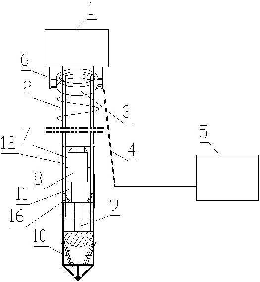
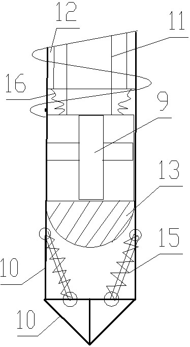
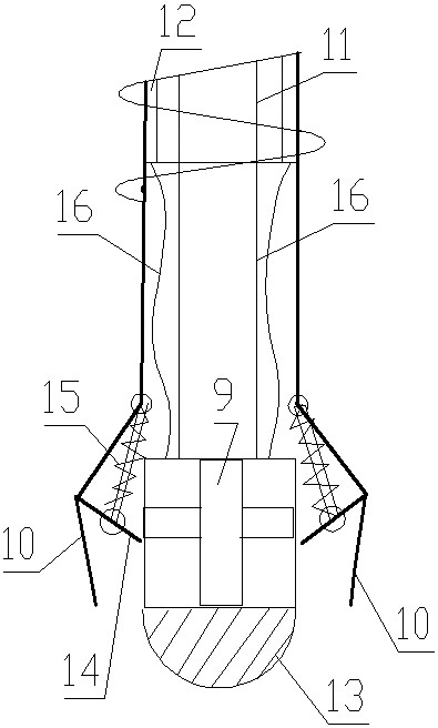
[0032] Such as Figure 1 to Figure 3 As shown, the long auger drilling rig integrated with drilling and compaction of the present invention is a mechanical device for completing the construction of cast-in-situ piles, including a chassis assembly, which has a traveling mechanism and a rotary table, and the rotary table is provided with a drilling tower and a driver's cab. The drilling tower is hoisted with a power head 1 through a suspension rope and a movable pulley device, and the power head 1 is used to move up and down along the tower body, and a long auger rod 2 is installed downward on the power head 1;

[0033] The top of the long auger rod 2 is connected with an air guide tube 4 through a rotary seal joint 3, and the air guide tube 4 is connected with an air pump 5; connect;

[0034] The lower part of the long auger rod 2 is provided with an installation cavity 7, and an electric push rod 8 is fixedly installed in the installation cavity 7, and the protruding rod 11 o...


PUM


Abstract

The invention discloses a long spiral drilling machine which is characterized in that an air guide pipe is connected to the top of a long spiral drilling rod through a rotary sealing joint, and an air pump is connected to the air guide pipe; an electric push rod is mounted at the lower part of the long spiral drilling rod; an extension rod of the electric push rod is downwards connected with an air hammer; an air guide hole is formed in the long spiral drilling rod in the vertical direction, the upper end of the air guide hole communicates with an air guide pipe through a rotary sealing joint, and the lower end of the air guide hole is connected with the air hammer through a hose; a plurality of drill bit frames are uniformly hinged to the long spiral drilling rod at the bottom end of a mounting cavity in the circumferential direction; an electric brush device is arranged on the long spiral drilling rod at the rotary sealing joint; and a connecting line of the electric push rod is led out of the long spiral drilling rod through the electric brush device and is connected with an electric control device in a cab. By using the drilling machine, cross operation of various mechanical equipment is not needed any more, so that the time for moving large equipment back and forth is saved, and the construction efficiency is greatly improved. A rammer compactor is not needed any more, so that the construction equipment cost is obviously reduced.

Description

technical field [0001] The invention relates to the field of building engineering, in particular to the technical field of building pile foundation construction, in particular to a long auger drilling machine for building pile foundation construction. Background technique [0002] The rapid economic development has brought certain pressure to construction engineering technology. Especially for the increasing height and number of high-rise buildings in cities, it not only requires the construction personnel to improve the relevant technology and level, but also has higher and higher requirements for construction equipment. In order to improve the bearing capacity of the foundation, the introduction of compaction pile construction technology in foundation treatment has received more and more attention and recognition from architects. According to the hole forming method, it can be divided into several types such as vibrating immersed tube, hammering immersed tube, impact or d...

Claims


Application Information

Patent Timeline
Patent Type & Authority Applications(China)
IPC IPC(8): E21B3/02E21B11/00E21B12/00E21B17/22E02D3/046
CPCE21B3/02E21B11/00E21B12/00E21B17/22E02D3/046
Inventor 贺伟娟李佩奇李亮亮李俊贺兆阳娄喜战张凯畅玉朋李一时亚军
Owner 河南云平环保科技有限公司
Why Eureka
Eureka Blog
Learn More