
Broken bridge heat insulation door and window

A technology for thermal insulation of broken bridges and doors and windows, which is applied in door/window protection devices, special equipment for doors/windows, windows/doors, etc., and can solve the problem of large frame, multiple indoor space resources, installation and disassembly of frame and other problems to achieve the effect of avoiding dust absorption and saving indoor space resources

Inactive Publication Date: 2021-07-23
武汉市绍阳科技有限公司
View PDF3 Cites 0 Cited by
  • Summary
  • Abstract
  • Description
  • Claims
  • Application Information

AI Technical Summary

Problems solved by technology

[0004] ①. The existing frame for installing glass is to slot the wall, then install the frame, and then directly seal it with bricks and cement. This design is very convenient for the installation and disassembly of the frame Both are more troublesome, which makes it more difficult to maintain the doors and windows in the later stage, and some frame frames are larger. For the convenience of transportation, the frame frame is designed into multiple sections, which are assembled into the frame frame of the required shape by splicing when in use, but When splicing these frame frames, there is not a good connection mechanism that can make the frame frame splicing very complete
[0005] ②. After the existing broken bridge insulation doors and windows are installed, it is necessary to install curtains on the indoor walls, and installing curtains on the indoor walls will occupy more indoor space resources, and will also affect the convenience of personnel activities and work Sex, and the dust floating in the air is easy to adhere to the curtains, so it takes extra time and energy to clean the curtains

Method used


Image

  • Broken bridge heat insulation door and window
  • Broken bridge heat insulation door and window
  • Broken bridge heat insulation door and window

Examples


Embodiment Construction

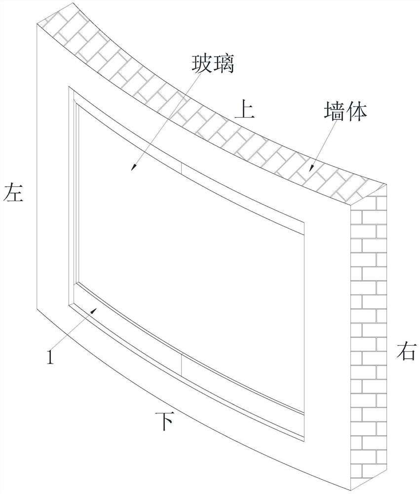
[0034] In order to make the technical means realized by the present invention, creative features, goals and effects easy to understand, the following combination Figure 1 to Figure 9 , to further elaborate the present invention.

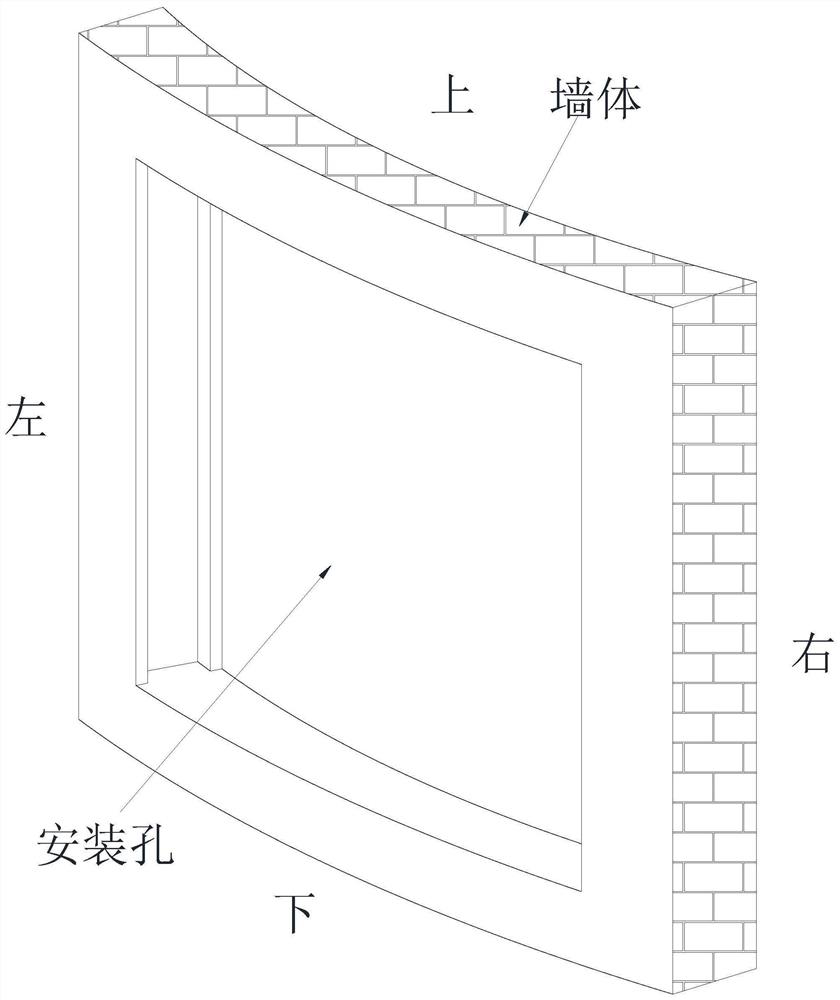
[0035] A broken bridge insulated door and window, which includes a frame body 1 and a connecting mechanism 2. There are installation holes on the wall body. The two framed bodies 1 are connected by a connecting mechanism 2 before, and two pieces of glass are installed sequentially in the two framed bodies 1; wherein:

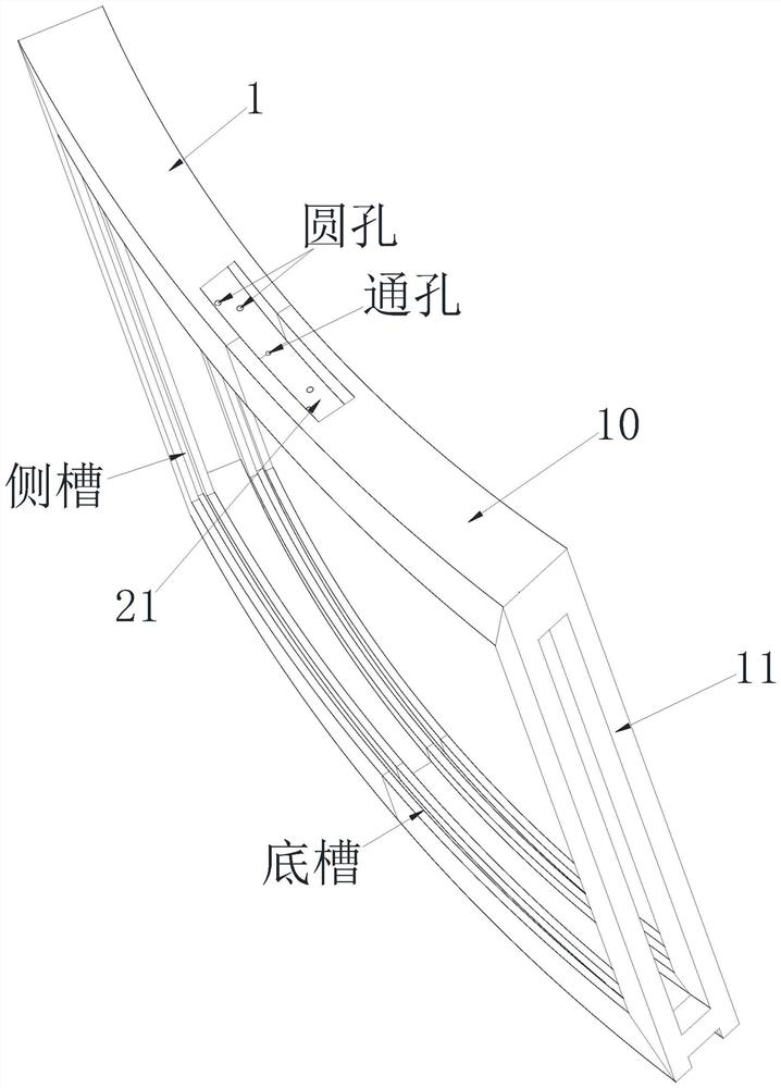
[0036]The frame body 1 is divided into two bottom frames 10 and a side frame 11, the bottom frame 10 is designed into an arc structure according to the shape of the wall, the side frame 11 is a strip structure, and the ends of the bottom frame 10 are connected to the The ends of the side frame 11 are vertically connected, the side of the bottom frame 10 away from the wall is symmetrically provided with two bottom grooves along its wi...


PUM


Abstract

The invention relates to a broken bridge heat insulation door and window. The broken bridge heat insulation door and window comprises edge wrapping frame bodies and a connecting mechanism, a mounting hole is formed in a wall body, the edge wrapping frame bodies are symmetrically mounted in the mounting hole in the length direction of the mounting hole, the two edge wrapping frame bodies are connected through the connecting mechanism, and two pieces of glass are jointly and sequentially mounted in the two edge wrapping frame bodies. According to the broken bridge heat insulation door and window, the problems existing at present that the door and window are difficult to maintain in the later period due to the fact that the edge wrapping frame bodies are troublesome to mount and dismount, when the edge wrapping frame bodies are spliced, no good connecting mechanism can enable the edge wrapping frame bodies to be spliced very completely, and in the prior art, a curtain needs to be installed on an indoor wall, more indoor space resources are occupied when the curtain is installed on the indoor wall, convenience of activity and work of people is affected, dust floating in air is prone to being attached to the curtain, and therefore extra time and energy are needed for cleaning the curtain can be solved.

Description

technical field [0001] The invention relates to the field of door and window design, in particular to a broken bridge insulation door and window. Background technique [0002] The principle of the broken bridge insulation door and window is to penetrate the heat insulation strip in the middle of the profile, and the profile is broken to form a broken bridge, which can effectively prevent the conduction of heat. Glue, styrofoam, sealing strips, etc., and the doors and windows processed in this way are called broken bridge insulation doors and windows. The outstanding advantages of broken bridge insulation doors and windows are high strength, good thermal insulation, good rigidity, good fire resistance, large lighting area, good atmospheric corrosion resistance, high comprehensive performance, long service life and good decorative effect. [0003] At present, the following problems exist in the design of broken bridge insulation doors and windows: [0004] ①. The existing fr...

Claims


Application Information

Patent Timeline
IPC IPC(8): E06B3/263E06B1/60E06B3/677E06B7/28E06B9/264
CPCE06B3/263E06B3/26305E06B1/6015E06B3/677E06B9/264E06B7/28
Inventor 吴小庆
Owner 武汉市绍阳科技有限公司
Learn More