


Quick Research
Generate reliable direction feasibility study reports for your R&D in just a few steps.

Technical Q&A
Discover and master advanced knowledge NOW. Basics, ideas, possibilities, all at once.

Find Solutions
As an expert in R&D theories, this can generate solutions to your technical problems instantly.

Evaluate Feasibility
Analyze your overall solution with one click, know your potential R&D risks in advance.

Monitor Landscape
Get weekly tech updates, stay abreast of the latest tech innovations and key insights.
Passive containment heat export system with flow guide structure
A passive containment and heat export technology, which is applied in the field of passive safety systems of nuclear reactors, can solve the problems of affecting the condensation heat transfer effect, not receiving enough attention, reducing the heat transfer efficiency of the heat exchanger, etc., to improve the gas flow condition , ensuring safety, reducing the effect of weakening
- Summary
- Abstract
- Description
- Claims
- Application Information
AI Technical Summary
Problems solved by technology
Method used
Image


Examples
Embodiment 1
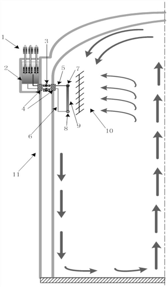
[0030] Such as figure 1 As shown, a passive containment heat export system with a diversion structure according to the present invention is arranged on the inside and outside of the containment 11, including the inner part of the containment and the outer part of the containment; the inner part of the containment Located on the upper part of the inner side wall of the containment, the main body includes an internal heat exchanger and a flow guide structure; the outer part of the containment is located above the outer side wall of the containment, and the main structure includes an external cooling water tank and a steam-water separator; the inner part of the containment It is connected with the outer part of the containment through pipelines and valves.
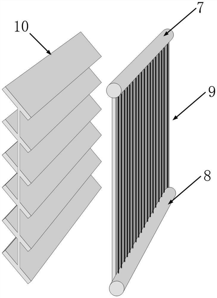
[0031] The flow guide structure of the inner part of the containment is arranged parallel to the internal heat exchanger, which is a louver-type flow guide structure 10, and the blades are made of rectangular stainless steel ...
Embodiment 2
[0037] Such as figure 1 As shown, a passive containment heat export system with a diversion structure according to the present invention is arranged on the inside and outside of the containment 11, including the inner part of the containment, the outer part of the containment, and the part connected to the inner part of the containment , pipelines on the outer part of the containment;
[0038] The outer part of the containment vessel includes a heat pipe 1 and an external cooling water tank 2; wherein, the external cooling water tank 2 is arranged above the outer side wall of the containment vessel, and the heat pipe 1 is arranged in the external cooling water tank 2 to strengthen the cooling of the external cooling water tank 2 ;
[0039] The inner part of the containment includes a heat exchange tube 9, an upper header 7 of the heat exchanger, a lower header 8 of the heat exchanger, and a flow guide structure 10; wherein, the upper end of the heat exchange tube 9 is connect...
Embodiment 3
[0047] Such as figure 1 As shown, a reactor with the passive containment heat extraction system described in Embodiment 1 or Embodiment 2. The passive containment cooling system includes a containment inner part and a containment outer part. The inner part of the containment vessel is located inside the containment vessel, and the main body includes an internal heat exchanger and a flow guide structure; the outer part of the containment vessel is located above the outer side wall of the containment vessel, and the main structure includes an external cooling water tank and a steam-water separator. The inner part of the containment vessel is connected with the outer part through pipelines and valves.
[0048] The outer part of the containment includes a heat pipe 1, an external cooling water tank 2, an inlet and outlet isolation valve 3, a penetration piece 4, an ascending pipeline 5 and a descending pipeline 6; the external cooling water tank 2 is arranged at a high place outs...
PUM
 Abstract
Description
Claims
Application Information
 - R&D Engineer
- R&D Manager
- IP Professional
- Industry Leading Data Capabilities
- Powerful AI technology
- Patent DNA Extraction
Browse by: Latest US Patents, China's latest patents, Technical Efficacy Thesaurus, Application Domain, Technology Topic, Popular Technical Reports.
© 2024 PatSnap. All rights reserved.Legal|Privacy policy|Modern Slavery Act Transparency Statement|Sitemap|About US| Contact US: help@patsnap.com