
A corrosion-resistant tail rudder and wind-driven generator

A corrosion-resistant and tail rudder technology, which is applied in the direction of wind turbines, wind turbine control, wind power generation, etc., can solve problems such as the inability to adjust the tail rudder tilt bar, poor corrosion resistance of the tail rudder, and poor fatigue resistance, etc., to achieve Light weight, good bending resistance, and the effect of improving fatigue strength

Active Publication Date: 2022-04-22
广州赛特新能源科技发展有限公司
View PDF0 Cites 0 Cited by
  • Summary
  • Abstract
  • Description
  • Claims
  • Application Information

AI Technical Summary

Problems solved by technology

[0004] The purpose of the present invention is to solve the problem that the slant bar on the tail rudder cannot be adjusted during the use of the wind power generator, and the hardness is relatively strong, and the degree of fatigue resistance is poor during operation, which eventually leads to the tail rudder being prone to breakage, and the tail rudder The problem of poor corrosion resistance

Method used


Image

  • A corrosion-resistant tail rudder and wind-driven generator
  • A corrosion-resistant tail rudder and wind-driven generator
  • A corrosion-resistant tail rudder and wind-driven generator

Examples


Embodiment 1

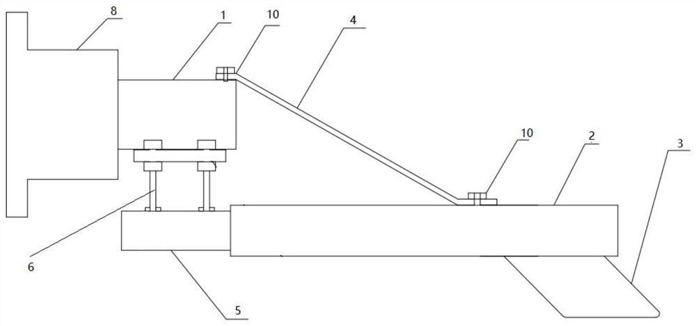
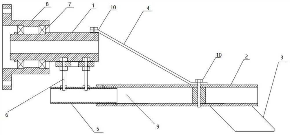
[0034] Please refer to the attached figure 1 , attached figure 2 , Embodiment 1 of the present invention proposes a corrosion-resistant tail rudder, including a connection mechanism, an anti-vibration cable-stay adjustment mechanism, and a tail rudder mechanism;

[0035] The connecting mechanism includes a first connecting piece 1;

[0036] The tail rudder mechanism includes a tail boom 2 and a tail fin plate 3 installed on the bottom surface of the tail boom 2 away from the end of the first connecting piece 1;

[0037] The anti-vibration cable-stay adjustment mechanism includes an adjustable component, a cable-stay rod 4 and a second connector 5 located below the first connector 1 , and one end of the cable-stay rod 4 passes through the upper surface of one end of the first connector 1 . The bolt 10 is fixedly connected, the other end of the diagonal stay rod 4 is fixedly connected with the upper surface of the tail rod 2 through the bolt 10, and one end of the adjustable ...

Embodiment 2

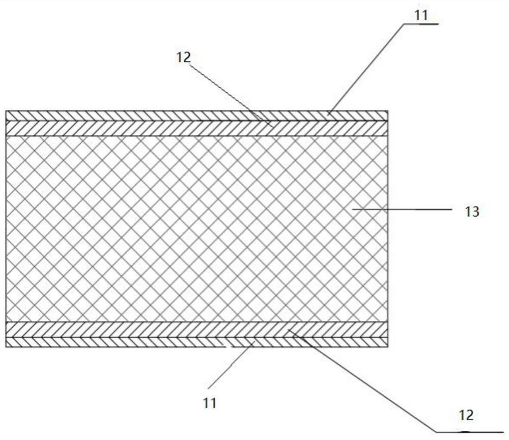
[0051] Please refer to the attached figure 1 , attached figure 2 , attached image 3 , Embodiment 2 of the present invention proposes a wind-driven generator, including a generator, a generator main shaft, a generator cabin, a fan pole, a wind wheel, and a corrosion-resistant tail as described in any one of the above-mentioned Embodiment 1. Rudder, the bearing seat 8 of the tail rudder is connected with one end of the generator cabin through the tail rudder connecting plate. Since the connection structure between the generator, the generator main shaft, the generator cabin, the fan pole, the wind wheel and the tail rudder belongs to the prior art, it will not be described in detail in this embodiment, and those skilled in the art will refer to the prior art that is Yes, and the specific structure of the tail rudder can be referred to the first embodiment above.

[0052] Specifically, in the embodiment of the present invention, the structure of the main shaft of the generat...


PUM


Abstract

The invention relates to the technical field of wind power generation equipment, in particular to a corrosion-resistant tail rudder and a wind power generator. The tail rudder includes a connection mechanism, an anti-vibration cable-stay adjustment mechanism and a tail rudder mechanism; the connection mechanism includes a first connector; the tail rudder mechanism includes a tail boom and an empennage plate; the anti-shock cable-stay adjustment mechanism includes an adjustable component, a diagonal stay rod and a second connecting piece, one end of the diagonal stay rod is fixedly connected to the first connecting piece, the other end is fixedly connected to the tail rod, one end of the adjustable component is connected to the first connecting piece, and the other end It is connected with the second connecting piece, and one end of the second connecting piece is movably socketed with one end of the tail rod. When the tail boom is running, the distance between the first connecting piece and the second connecting piece can be adjusted by controlling the adjusting bolt, so as to further adjust the diagonal stay rod, which can effectively improve the resistance of the diagonal stay rod. The fatigue strength avoids the problem that the tail rudder is prone to breakage.

Description

technical field [0001] The invention relates to the technical field of wind power generation equipment, in particular to a corrosion-resistant tail rudder and a wind power generator. Background technique [0002] With the rapid development of wind power generation, its own limitations are gradually revealed. Although wind energy is sustainable, because the wind direction and wind speed are always changing, if you want to obtain a high wind energy utilization rate, you must make the wind wheel follow the wind direction, which puts forward strict requirements for the yaw control of the wind turbine. The yaw system can make the wind rotor automatically face the wind under the normal range of wind speed. Due to the large weight of the wind turbine itself, when the wind direction changes, the wind rotor can only achieve discontinuous deflection. Most of the time there will be an angle between the wind rotor and the wind direction, which will affect the power generation efficienc...

Claims


Application Information

Patent Timeline
Patent Type & Authority Patents(China)
IPC IPC(8): F03D7/02F03D80/00
CPCF03D7/0204F03D80/00Y02E10/72
Inventor 王亮海朱明
Owner 广州赛特新能源科技发展有限公司
Learn More