Water tank hoisting device for water tower and construction method of water tank

A hoisting device and water tank technology, applied in the direction of transportation and packaging, load hanging components, formwork/formwork/work frame, etc., can solve the problems of waste of human resources during the construction period, affect the quality of the project, shaking, etc., and save manpower and construction period Effect

Active Publication Date: 2021-07-20
武汉京冶中城建设有限公司
View PDF8 Cites 0 Cited by
  • Summary
  • Abstract
  • Description
  • Claims
  • Application Information

AI Technical Summary

Problems solved by technology

[0003] In the existing construction method, after the sliding form construction of the support tube is completed, the sliding form device is usually removed, and then the water tank is poured on the outside of the support tube. The pulley block hoisting device is used to lift along the support tube; the existing water tank hoisting method will cause shaking during the hoisting process, which will cause friction and collision between the water tank and the support tube during the hoisting process, and easily damage the water tank and the support tube. There are also potential safety hazards in the quality of the project; at the same time, if the lifting device such as the pulley hoisting group is installed on the top of the support tube, the sliding form device needs to be removed, and the removal of the sliding form device and the installation of the lifting device will also take a certain amount of time, which will cause a lot of construction time and human resources. waste

Method used


Image

  • Water tank hoisting device for water tower and construction method of water tank
  • Water tank hoisting device for water tower and construction method of water tank
  • Water tank hoisting device for water tower and construction method of water tank

Examples


Embodiment 1

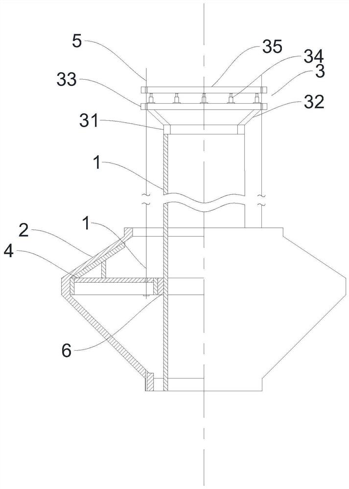
[0032] In this example, if figure 1 As shown, a water tank hoisting device for a water tower includes a support tube 1 and a water tank 2. The support tube 1 is made by a sliding form construction method. The water tank 2 is installed on the top of the support tube 1 through a hoisting device. The hoisting device includes a lifting device 3 and a stable device 4, and the lifting device 3 and the stabilizing device 4 are connected by several steel strands 5, the lifting device 3 is installed on the top of the support tube 1, and the stabilizing device 4 is installed between the support tube 1 and the water tank 2, the hoisting device of the present invention A stabilizing device 4 is provided, which can effectively prevent the water tank 2 and the support tube 1 from being damaged due to collision during the hoisting process, thereby affecting the project quality and causing potential safety hazards;

[0033] In this example, if Figure 1~4 As shown, the stabilizing device 4 i...

Embodiment 2

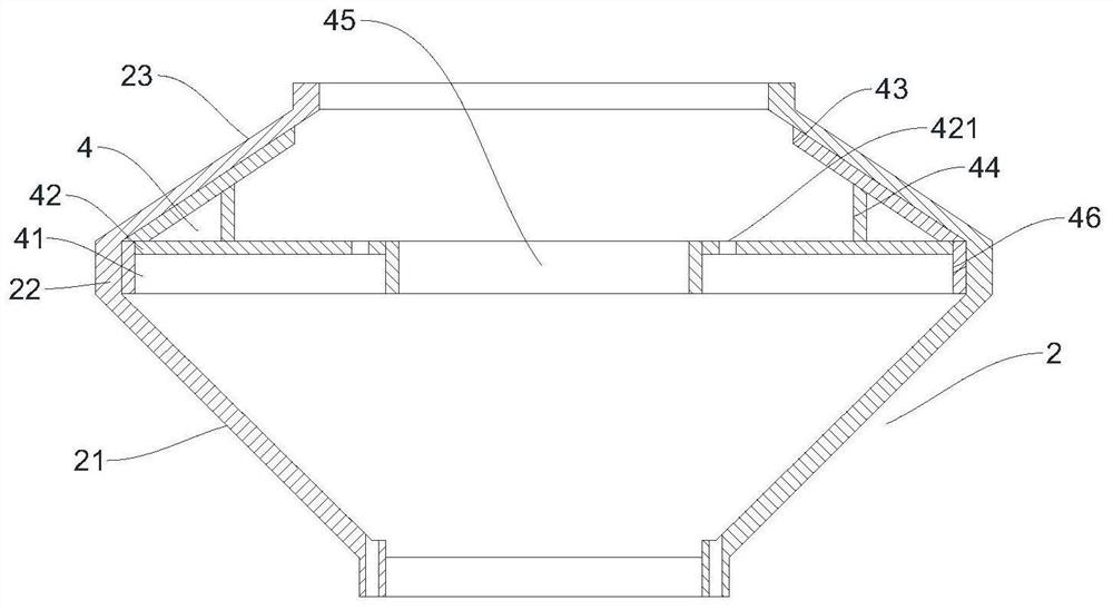
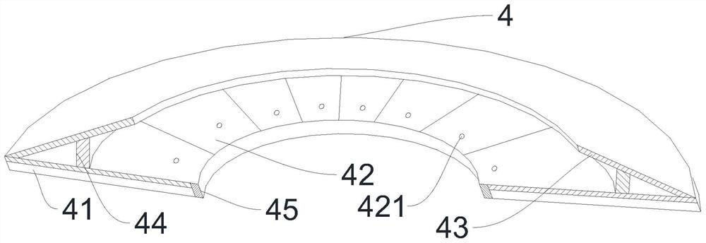
[0036] In this example, if Figure 1~4 As shown, the present embodiment increases the first vertical support 42 on the basis of the first embodiment, and several first vertical supports 41 are also arranged between the outer wall of the inner steel ring 45 and the inner wall of the outer steel ring 46. 41 are evenly distributed on the bottom of the annular plate 42, and the first vertical support 42 is used to strengthen the connection between the inner steel ring 45, the outer steel ring 46 and the annular plate 42. At the same time, when the steel strand 5 lifts the annular plate 42, Reinforce the annular plate 42 to prevent the annular plate 42 from being damaged when the water tank 2 is hoisted due to insufficient rigidity.

Embodiment 3

[0038] In this example, if figure 1 As shown, this embodiment adds a filling layer 6 on the basis of the second embodiment, the filling layer 6 is arranged between the inner steel ring 45 and the support tube 1, and the filling layer 6 is installed on the inner steel ring 45 for further buffering impact force, while avoiding direct contact friction between the inner steel ring 45 and the support tube 1, contacting and damaging the surface of the support tube 1, therefore, the filling layer 6 should be selected to be lower in strength, hardness and stiffness than the support tube 1 and the inner steel ring 45 The material is made of a material with strong wear resistance. Specifically, the support tube 1 is made of concrete, and the inner steel ring 45 is made of Q235-B material. Preferably, the filling layer 6 is made of polytetrafluoroethylene.


PUM


Abstract

The invention discloses a water tank hoisting device for a water tower. The water tank hoisting device for the water tower comprises a supporting cylinder and a water tank, wherein a stabilizing device is installed between the supporting cylinder and the water tank and comprises an inner steel ring, an outer steel ring and an annular plate; the inner wall of the inner steel ring abuts against the outer wall of the supporting cylinder; the outer steel ring is installed on the water tank; the annular plate is arranged between the outer wall of the inner steel ring and the inner wall of the outer steel ring; and steel strands are connected with the annular plate. The invention relates to a construction method of the water tower. The construction method of the water tower comprises the steps of installation of the stabilizing device and manufacturing of a lifting device. The water tank hoisting device for the water tower and the construction method of the water tank provided by the invention have the beneficial effects that the hoisting device provided by the invention is provided with the stabilizing device, and the stabilizing device can effectively avoid the possibility that the water tank and the supporting cylinder are damaged due to collision in the hoisting process, then the project quality is influenced, and potential safety hazards are caused; and according to the construction method provided by the invention, the installation of the hoisting device and the disassembly of a slip form device are synchronously carried out, and the slip form device is partially disassembled and partially transformed at the same time, so that compared with a traditional water tower construction method, a large amount of manpower is saved, and the construction period is shortened.

Description

technical field [0001] The invention belongs to the field of water tower construction facilities and methods, and in particular relates to a water tower water tank hoisting device and a construction method thereof. Background technique [0002] A water tower is a towering structure used for water storage and distribution. It is used to maintain and adjust the water volume and water pressure in the water supply network. It is mainly composed of a water tank and a support or bracket connecting the two. Nowadays, large water towers are usually constructed by slipform To build, slipform construction is a construction method in which a hydraulic lifting device is used to slide up the formwork to pour a vertical concrete structure. It is based on the plane shape of the building, and a complete set of hydraulic slipform devices (formwork, formwork, etc.) are placed on the ground or at a certain elevation Enclosure, lifting frame, operating platform, support rod and hydraulic liftin...

Claims


Application Information

Patent Timeline
IPC IPC(8): E04G11/22E04G11/24B66C1/12B66C13/06B66C13/20F16F15/02
CPCE04G11/22E04G11/24B66C1/12B66C13/06B66C13/20F16F15/02Y02A20/00
Inventor 叶志钢
Owner 武汉京冶中城建设有限公司
Why Eureka
Try Eureka