Deformable roller passing structure capable of automatically adjusting tension of pole piece

A technology of automatic adjustment and tension adjustment mechanism, which is applied in the directions of winding strips, thin material processing, transportation and packaging, etc., which can solve the problems of cumbersome operation, non-automatic adjustment, uneven tension, etc., and achieve the solution of slack, Reduces wrinkling effect

Active Publication Date: 2021-07-20
HEFEI GUOXUAN HIGH TECH POWER ENERGY
View PDF28 Cites 3 Cited by
  • Summary
  • Abstract
  • Description
  • Claims
  • Application Information

AI Technical Summary

Problems solved by technology

[0002] In the production process of power batteries, during the operation of coating machines, rolling, winding and other equipment, the tension of the incoming lithium battery foil is uneven, and one end of the incoming foil is loose in the width direction and the other is tight, resulting in frequent needs in production. Adjust the levelness and parallelism of the passing rolls of the equipment, but the degree of tension unevenness of each roll is different, and it is necessary to repeatedly adjust the installation accuracy of the passing rolls of the equipment. This operation is cumbersome, time-consuming and laborious, and cannot be realized for the actual situation of uneven tension of each roll auto-adjust

Method used


Image

  • Deformable roller passing structure capable of automatically adjusting tension of pole piece
  • Deformable roller passing structure capable of automatically adjusting tension of pole piece
  • Deformable roller passing structure capable of automatically adjusting tension of pole piece

Examples


Embodiment Construction

[0017] In the description of the present invention, unless otherwise specified, the orientation or positional relationship indicated by the terms "upper", "lower", "left", "right", "front", "rear", etc. are only for describing the present invention and simplifying the description, rather than Nothing indicating or implying that the referred device or structure must have a particular orientation should not be construed as limiting the invention. In addition, the terms "first", "second", etc. are used for descriptive purposes only, and should not be construed as indicating or implying relative importance.

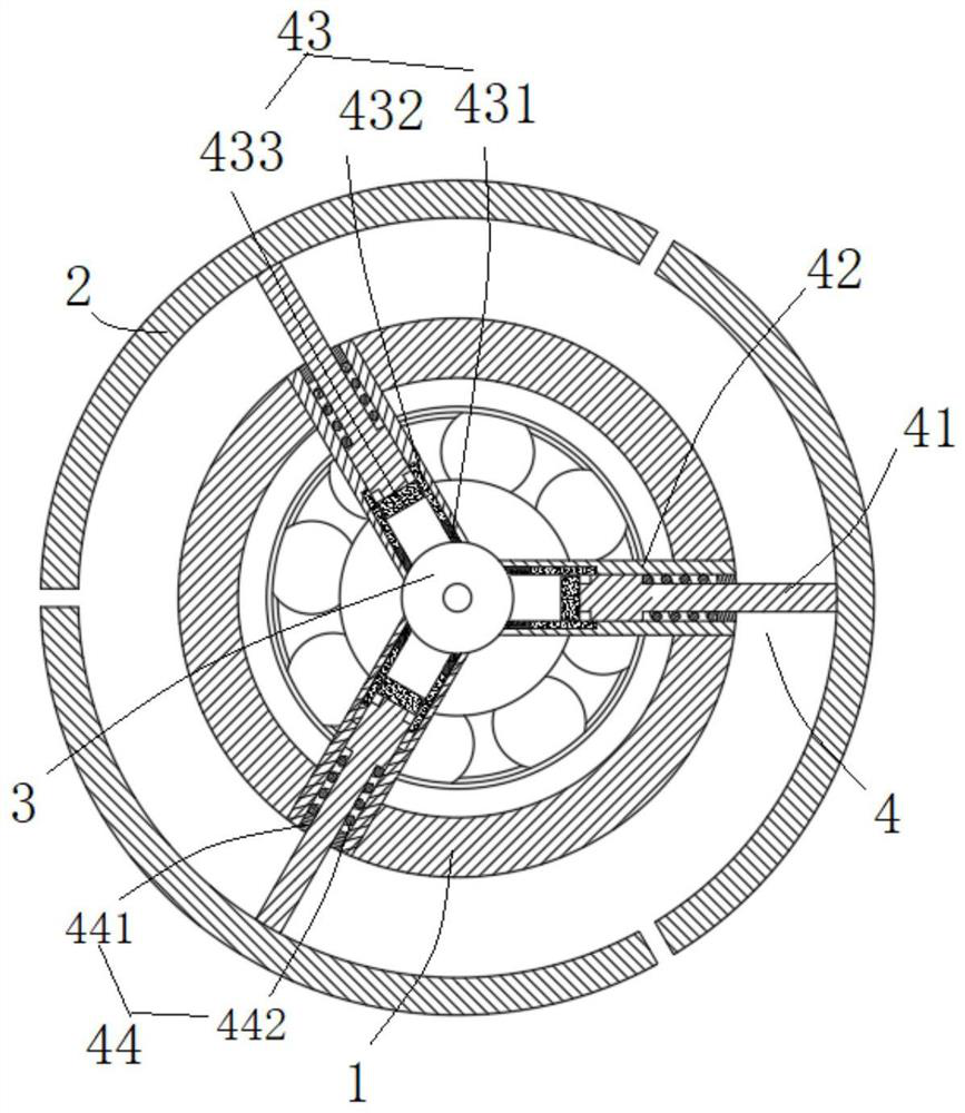
[0018] Such as figure 1 As shown, a deformable roller structure for automatically adjusting pole piece tension according to the present invention includes an inner roller 1 and an outer roller 2, a central shaft 3 and a tension adjustment mechanism 4, wherein the central shaft is arranged on the inner roller The roller is arranged concentrically with the inner roller, the ou...


PUM


Abstract

The invention discloses a deformable roller passing structure capable of automatically adjusting tension of a pole piece, which comprises an inner roller and an outer roller, a center shaft concentric with the inner roller is arranged in the inner roller, and the outer roller is composed of at least two sections of arcs forming a cylindrical structure; a tension adjusting mechanism connected with the inner roller is connected to the center shaft and comprises at least two guide rods correspondingly connected with the at least two sections of arcs and connecting frames connected to the inner roller and the center shaft and corresponding to the guide rods; and the guide rods are connected to the corresponding connecting frames in a sliding mode. The guide rods are displaced in the axial direction through the magnetic force of an electromagnetic rings and the elastic effect of springs, so that the diameter of the outer roller is adjusted, and the problem that the edge of supplied foil in the width direction is loosened in lithium battery piece production is effectively solved.

Description

technical field [0001] The invention belongs to the technical field of tension adjustment, and in particular relates to a deformable roller structure for automatically adjusting the tension of pole pieces. Background technique [0002] In the production process of power batteries, during the operation of coating machines, rolling, winding and other equipment, the tension of the incoming lithium battery foil is uneven, and one end of the incoming foil is loose in the width direction and the other is tight, resulting in frequent needs in production. Adjust the levelness and parallelism of the passing rolls of the equipment, but the degree of tension unevenness of each roll is different, and it is necessary to repeatedly adjust the installation accuracy of the passing rolls of the equipment. This operation is cumbersome, time-consuming and laborious, and cannot be realized for the actual situation of uneven tension of each roll auto-adjust. Contents of the invention [0003]...

Claims


Application Information

Patent Timeline
Patent Type & Authority Applications(China)
IPC IPC(8): B65H20/02B65H23/16B65H27/00
CPCB65H20/02B65H23/16B65H27/00B65H2701/173Y02E60/10
Inventor 李敏王友路叶明吴德
Owner HEFEI GUOXUAN HIGH TECH POWER ENERGY
Why Eureka
Try Eureka