
Magnetic attraction type printing head sheet

A printing head and magnetic suction technology, which is applied in printing and other directions, can solve the problems of inconsistent printing density, new users do not know how to open the cover, and different font depths, etc., to achieve the effect of protection from damage

Pending Publication Date: 2021-07-20
XIAMEN RONGTA TECH
View PDF9 Cites 0 Cited by
  • Summary
  • Abstract
  • Description
  • Claims
  • Application Information

AI Technical Summary

Problems solved by technology

[0003] First, the existing printers use springs to apply a pressure to the thermal head, and the thermal head relies on the pressure of the spring and the rubber roller to clamp the printing paper to achieve the printing effect of the printer. Such a structure is easy to cause The inconsistent pressure exerted by both ends of the spring will produce the effect of inconsistent printing density, that is, the printed fonts are of different shades;
[0004] Second, the opening and closing methods of existing printers (especially printers with wrong titles) are all connected by the hinge of the upper cover group and the bracket of the lower cover group. When opening and closing the cover, it is necessary to slide the buckle of the upper cover group to To open the paper compartment of the printer, such a structure requires a relatively large force to open the cover, and often new users do not know how to open the cover and get into embarrassment

Method used


Image

  • Magnetic attraction type printing head sheet
  • Magnetic attraction type printing head sheet
  • Magnetic attraction type printing head sheet

Examples


Embodiment 1

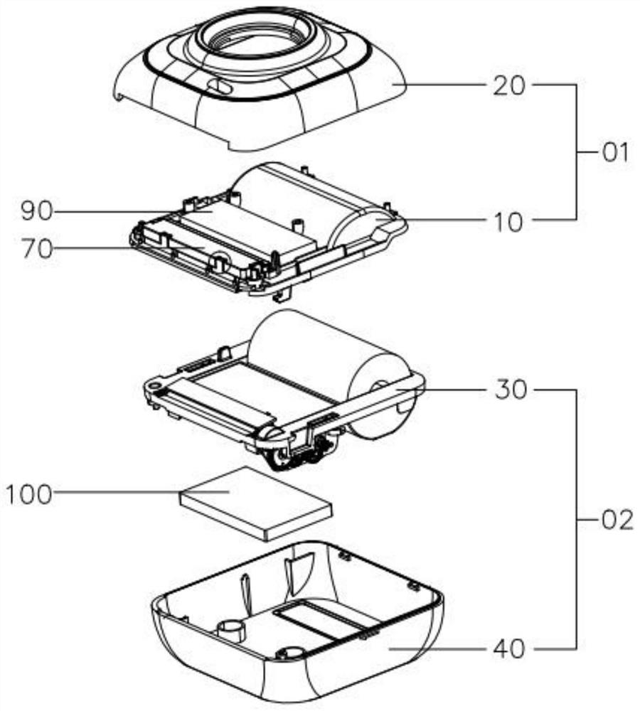
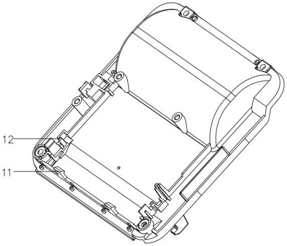
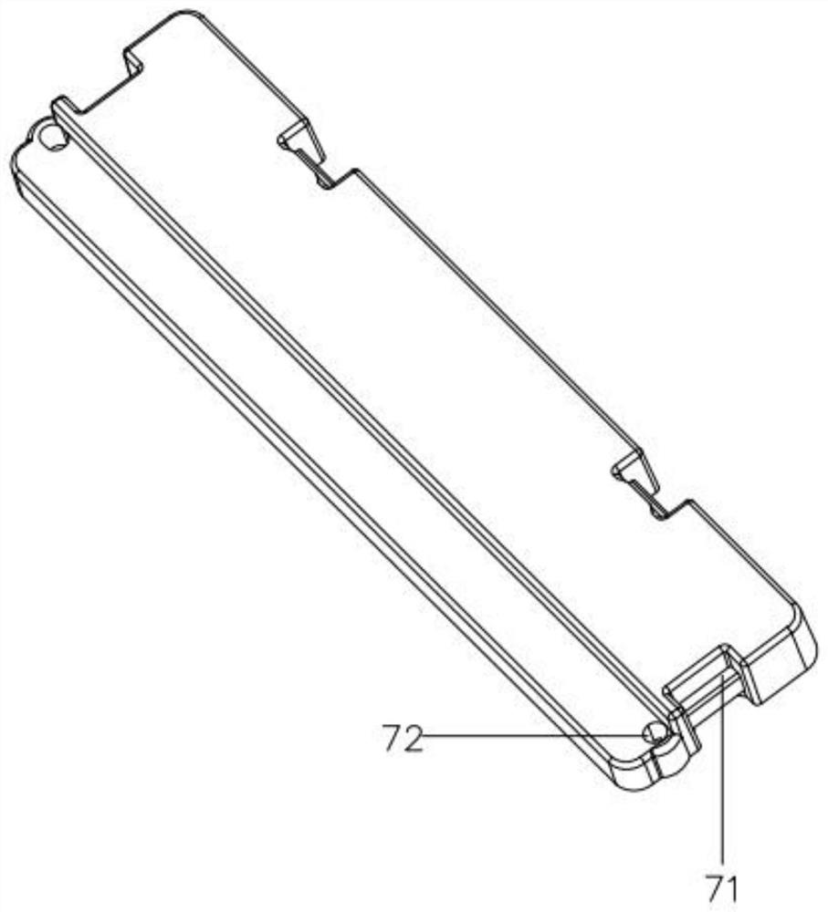
[0030] see Figures 1 to 6 , is a magnetic suction type print head sheet as Embodiment 1 of the present invention, including an upper bracket 10, a thermal print head sheet 50, and a first electromagnet 60 for fixing the thermal print head sheet 50, setting On the upper bracket 10 and the second electromagnet 70 corresponding to the first electromagnet 60, the first electromagnet 60 is movably connected with the upper bracket 10; specifically, the upper bracket 10 is provided with a place for placing the first electromagnet 60 slot, and is restricted in the placement slot by the second magnet.

[0031] This embodiment cancels the fixed structure of the original thermal printing head sheet 50, that is, a spring is used to exert a pressure on the head sheet, and the head sheet and the rubber roller 80 are closely attached to achieve the printing effect, but this structure is easy to be damaged due to the force of the spring. Different results in inconsistencies in printing dens...

Embodiment 2

[0034] see Figures 1 to 4 , is a kind of printer as embodiment 2 of the present invention, has adopted a kind of magnetic suction type print head sheet of embodiment 1 of the present invention; A third electromagnet 90 is provided, and a fourth electromagnet 100 corresponding to the third magnet is provided on the lower bracket 30 . The third electromagnet 90 and the fourth electromagnet 100 are attracted to each other to close the upper bracket 10 and the lower bracket 30 .

[0035] The printer also includes an upper casing 20 arranged outside the upper bracket 10, and a lower casing 40 arranged outside the lower bracket 30; the upper bracket 10 and the upper casing form the lower cover group 02, and the lower bracket 30 and the lower casing form the lower cover group 02, and the upper cover set 01 and the lower cover set 02 are detachably connected through the third electromagnet 90 and the fourth electromagnet 100. The third electromagnet 90 is disposed close to the side ...


PUM


Abstract

The invention provides a magnetic attraction type printing head sheet which comprises an upper support and a thermal printing head sheet. The magnetic attraction type printing head sheet further comprises a first electromagnet used for fixing the thermal printing head sheet and a second electromagnet arranged on the upper support and corresponding to the first electromagnet. The first electromagnet is movably connected with the upper support, and meanwhile the invention further provides a printer. The printer not only adopts the magnetic attraction type printing head sheet, but also comprises a lower support arranged opposite to the upper support. A third electromagnet is arranged on the upper support, a fourth electromagnet corresponding to the third electromagnet is arranged on the lower support, and the third electromagnet and the fourth electromagnet attract each other to realize covering of the upper support and the lower support. According to the magnetic attraction type printing head sheet, a second electromagnet piece matched with the first electromagnet is used for generating mutual repulsive magnetic force, so that the printing effect is achieved, when the first electromagnet and the second electromagnet generate mutual attraction magnetic force, the thermal printing head sheet is attracted back, and therefore the thermal printing head sheet can be better protected against damage.

Description

technical field [0001] The invention relates to the technical field of printers, in particular to a magnetic suction print head sheet. Background technique [0002] In modern society, due to the vigorous development of express delivery and other industries, there is a huge demand for portable printers that can be used outside. However, the existing portable printers have the following disadvantages: [0003] First, the existing printers use springs to apply a pressure to the thermal head, and the thermal head relies on the pressure of the spring and the rubber roller to clamp the printing paper to achieve the printing effect of the printer. Such a structure is easy to cause The inconsistent pressure exerted by both ends of the spring will produce the effect of inconsistent printing density, that is, the printed fonts are of different shades; [0004] Second, the opening and closing methods of existing printers (especially printers with wrong titles) are all connected by the...

Claims


Application Information

Patent Timeline
Patent Type & Authority Applications(China)
IPC IPC(8): B41J2/315
CPCB41J2/315
Inventor 许开明许开河郑长泉
Owner XIAMEN RONGTA TECH
Learn More