
Under-voltage tripping device for circuit breaker

A technology for undervoltage tripping and circuit breakers, which is applied in the direction of switches that operate when the voltage is lower than a predetermined value, protection switch operation/release mechanisms, etc., which can solve the inconvenience of installation, commissioning and maintenance, large installation space, and undervoltage releases. Complicated installation structure and other issues, to achieve the effect of facilitating installation, commissioning and maintenance, simplifying installation steps, and facilitating installation and disassembly operations

Pending Publication Date: 2021-07-16
ZHEJIANG PEOPLE ELE APPLIANCE
View PDF0 Cites 0 Cited by
  • Summary
  • Abstract
  • Description
  • Claims
  • Application Information

AI Technical Summary

Problems solved by technology

[0005] Therefore, the technical problem to be solved by the present invention is to overcome the fact that in the prior art, the release body part and the control circuit board are separately installed inside the circuit breaker, the installation space is relatively large, and the installation structure of the undervoltage release is complex, which is not easy To facilitate subsequent installation, commissioning and maintenance work, thereby providing an undervoltage tripping device with a compact structure, convenient installation and disassembly, convenient subsequent installation, commissioning and maintenance, and reliable realization of the undervoltage protection function of the circuit breaker

Method used


Image

  • Under-voltage tripping device for circuit breaker
  • Under-voltage tripping device for circuit breaker
  • Under-voltage tripping device for circuit breaker

Examples


Embodiment 1

[0038] Below in conjunction with accompanying drawing this embodiment is described in detail:

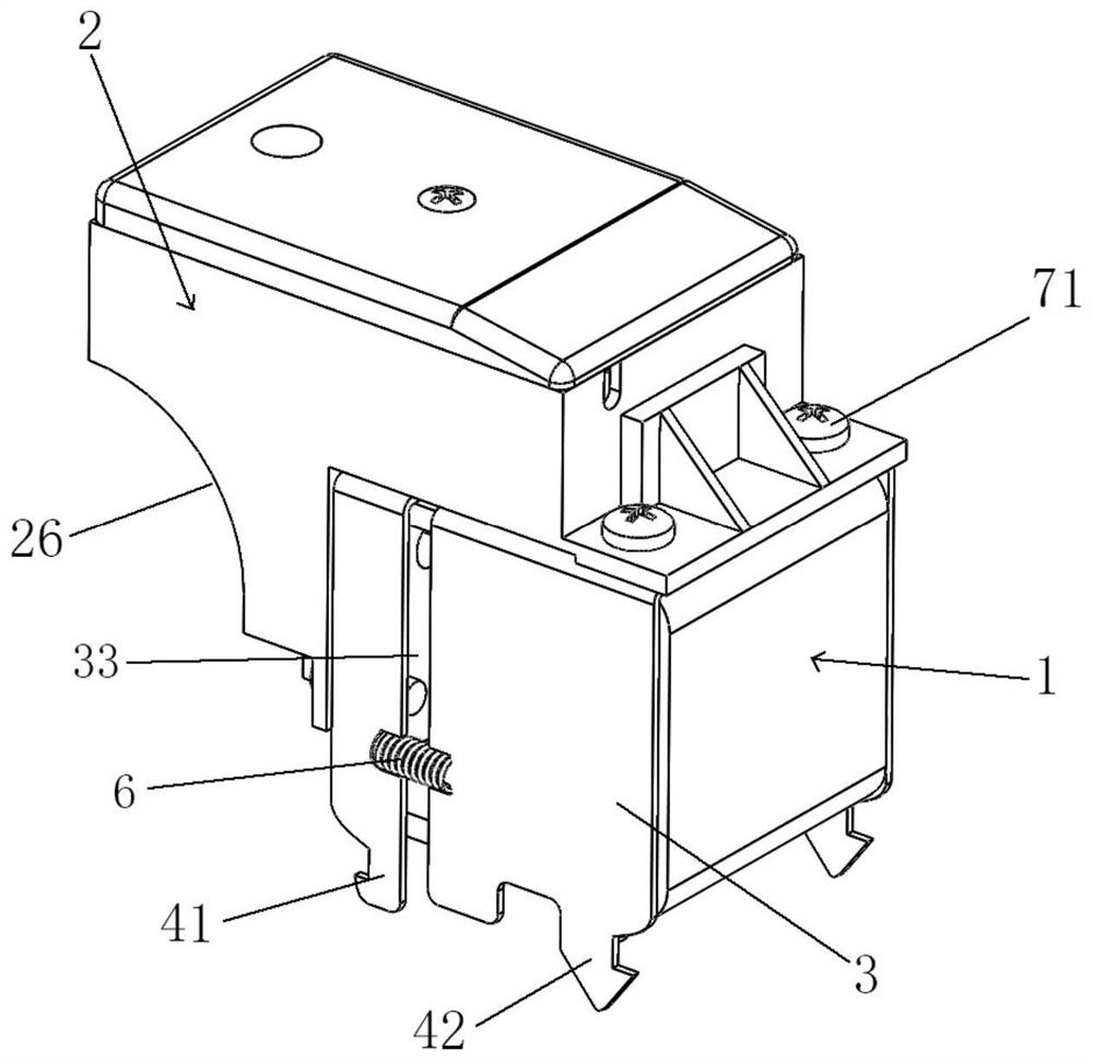
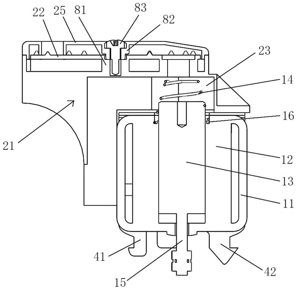
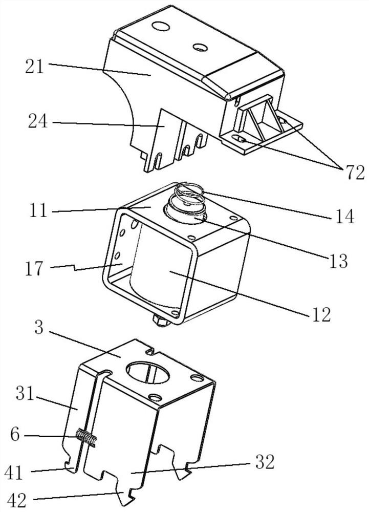
[0039] The present invention provides such Figure 1-7 The shown undervoltage tripping device for circuit breakers is connected to the operating mechanism 9 in the circuit breaker, and includes a tripper body 1 and a controller module 2. The tripper body 1 includes a movable The drive rod 15 pierced at the bottom of the release body 1, the controller module 2 is fixedly connected to the top of the release body 1 in a vertical shape, and the release body 1 is installed on the operating mechanism 9 In the groove space 91 formed between the upper part of the circuit breaker, and detachably connected to the top of the operating mechanism 9 through the installation structure, the top of the circuit breaker housing is provided with a panel covering the groove space 91, the installation structure include:

[0040] The installation frame 3 is semi-surrounded and arranged on the release bo...


PUM


Abstract

The invention discloses an under-voltage tripping device for circuit breaker. The under-voltage tripping device comprises a tripping device body and a controller module, the controller module is vertically fixed to the top of the tripping device body, the tripping device body is detachably connected to the top of an operating mechanism through a mounting structure, the mounting structure comprises a mounting frame arranged on the tripping device body, a baffle structure installed at the top of the operating mechanism, and clamping hook assemblies arranged at the bottom ends of two installation side plates of the mounting frame, the baffle structure is provided with clamping groove structures corresponding to the clamping hook assemblies, and release bodies are inserted into the clamping groove structures of the baffle structure through the clamping hook assemblies to form clamping fit. The under-voltage tripping device adopting the technical scheme realizes integrated installation, the overall structure is more compact, the installation steps are simplified, the installation and the disassembly are more convenient, the design is beneficial to the subsequent installation debugging and maintenance work of the under-voltage tripping device, the installation efficiency is improved, and the use performance of the product is improved.

Description

technical field [0001] The invention relates to the technical field of circuit breakers, in particular to an undervoltage tripping device for circuit breakers. Background technique [0002] The frame circuit breaker is an electrical appliance that not only has the function of manual switch, but also can automatically protect against voltage loss, undervoltage, overload, and short circuit. It can be used to distribute electric energy, start asynchronous motors infrequently, protect power lines and motors, and automatically cut off the circuit when they are seriously overloaded or short-circuited or under-voltage. [0003] In order to realize the undervoltage protection function of the frame type circuit breaker, it is often necessary to install and use an undervoltage release in the circuit breaker. A release that is opened, the coil of this undervoltage release is connected to the power supply side of the circuit breaker, and the circuit breaker can only be closed after the...

Claims


Application Information

Patent Timeline
IPC IPC(8): H01H71/10H01H83/12
CPCH01H83/12H01H71/10
Inventor 朱家逵刘添喜季勤雄蔡慧茂许建余龚艳冰何爱萍王惜晨王杰杨光鑫刘伦高学兵
Owner ZHEJIANG PEOPLE ELE APPLIANCE
Learn More