Multifunctional intelligent telemetering terminal based on micro-power consumption long-distance wireless connection

A wireless connection and telemetry terminal technology, applied in signal transmission systems, photovoltaic power generation, electric vehicles, etc., can solve the problems of consuming power supply equipment, inability to install detection devices in a timely and convenient manner, and difficult installation and disassembly of telemetry terminals. Consuming equipment, convenient disassembly and maintenance, and realizing the effect of micro power consumption

Inactive Publication Date: 2021-07-16
广西金智信息科技有限公司
View PDF7 Cites 0 Cited by
  • Summary
  • Abstract
  • Description
  • Claims
  • Application Information

AI Technical Summary

Problems solved by technology

[0005] Aiming at the deficiencies of the prior art, the present invention provides a multifunctional intelligent telemetry terminal based on micro-power long-distance wireless connection, which solves the problem that the telemetry terminal is not easy to install and disassemble, and new detection devices cannot be installed in a timely and convenient manner, and most of them require a separate The problem of power supply consumption of power supply equipment

Method used


Image

  • Multifunctional intelligent telemetering terminal based on micro-power consumption long-distance wireless connection
  • Multifunctional intelligent telemetering terminal based on micro-power consumption long-distance wireless connection
  • Multifunctional intelligent telemetering terminal based on micro-power consumption long-distance wireless connection

Examples


Embodiment

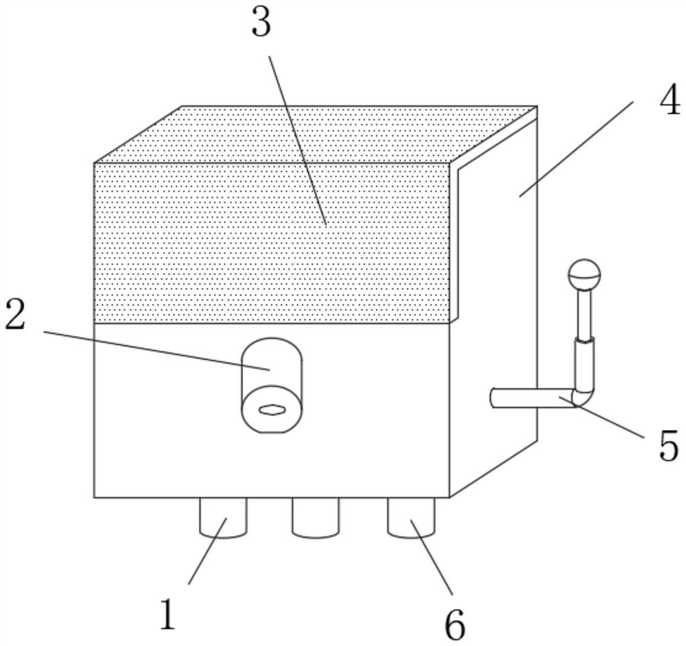
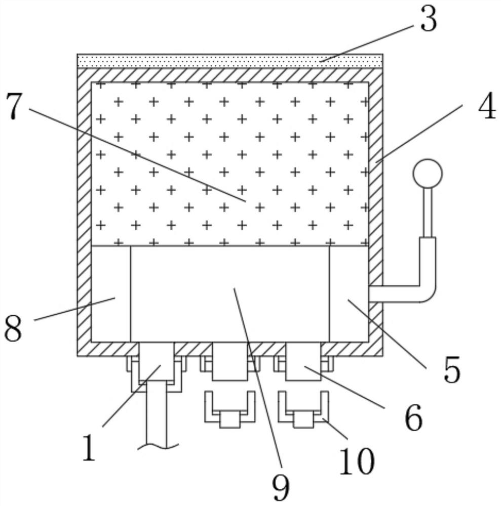
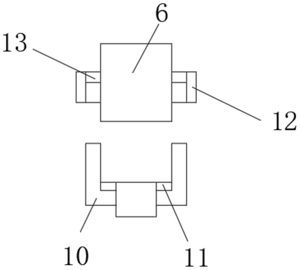
[0030] Such as Figure 1-6 As shown, the embodiment of the present invention provides a multi-functional intelligent telemetry terminal based on micro-power long-distance wireless connection, including a box body 4, and a solar photovoltaic panel 3 is arranged on the top of the box body 4, and the solar photovoltaic panel 3 can provide each The power supply of various components enables the telemetry terminal to be well used without additional power consumption. A camera 2 is installed in the middle of the front wall of the box body 4. The use environment around the box body 4 can be seen intuitively through the camera 2, so that the surrounding environment of the telemetry terminal is intuitive. It can be seen that, for a long-distance telemetry terminal, a battery 7 is arranged on the top of the box body 4, a control motherboard 9 is arranged at the middle of the bottom end of the box body 4, and an external connector interface 1 is arranged on the left side of the bottom end...


PUM


Abstract

The invention provides a multifunctional intelligent telemetering terminal based on micro-power consumption long-distance wireless connection, and relates to the field of telemetering terminals. The multifunctional intelligent telemetering terminal based on micro-power consumption long-distance wireless connection comprises a box body, a solar photovoltaic panel is arranged at the top of the box body, a control mainboard is arranged in the middle of the bottom end in the box body, and an external connector interface is formed in the left side of the bottom end of the control mainboard; standby interfaces are formed in the middle and the right side of the bottom end of the control mainboard, a mounting block is fixedly connected to the upper portion of the rear end of the box body, a sliding groove is formed in the bottom in the mounting block, a threaded rod is transversely connected to the middle of the mounting block in a threaded mode, and a hanging block is arranged in the sliding groove in a sliding mode and fixedly connected to the middle of the front end of a mounting plate. The telemetering terminal is convenient to overhaul through the sliding groove and the hanging block, new equipment can be installed on the telemetering terminal through the standby interface, wireless long-distance transmission can be well achieved through Bluetooth and GPRS equipment, and the telemetering terminal is worthy of being popularized vigorously.

Description

technical field [0001] The invention relates to the technical field of telemetry terminals, in particular to a multifunctional intelligent telemetry terminal based on micro-power consumption and long-distance wireless connection. Background technique [0002] The telemetry terminal integrates data collection, transmission, and storage functions, and adopts a low-power design. It is especially suitable for monitoring sites powered by solar energy. It can greatly reduce power supply costs and reduce construction difficulties. It is widely used in meteorology, hydrology and water conservancy, geology and other industries. [0003] There are three points that need to be improved when the existing telemetry terminal is in use. One is that the telemetry terminal is not easy to disassemble and install during regular maintenance and repair, which delays the progress of the telemetry terminal’s maintenance. Second, when the telemetry terminal is in use, it is usually It is connected ...

Claims


Application Information

Patent Timeline
IPC IPC(8): G08C17/02H05K5/02H02J7/35
CPCG08C17/02H05K5/0217H05K5/0204H02J7/35Y02E10/56
Inventor 黄克强梁家精黄定谋
Owner 广西金智信息科技有限公司
Why Eureka
Try Eureka